


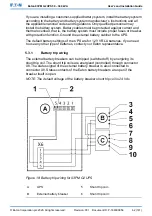


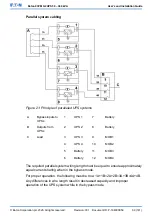

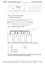


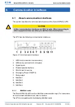


Parallel system cabling
Figure 21: Principle of paralleled UPS systems
A
Bypass inputs to
UPSs
1
UPS 1
7
Battery
B
Outputs from
UPSs
2
UPS 2
8
Battery
C
Load
3
UPS 3
9
MOB1
4
UPS 4
10
MOB2
5
Battery
11
MOB3
6
Battery
12
MOB4
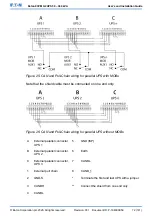
The required parallel system wiring length must be equal to ensure approximately
equal current sharing when in the bypass mode.
For proper operation, the following must be true: 1A+1B=2A+2B=3A+3B=4A+4B.
Any differences in wire length result in decreased capacity and improper
operation of the UPS system while in the bypass mode.
© Eaton Corporation plc 2020. All rights reserved.
Revision: 001
Document ID: P-164000956
69 (141)
Eaton 93PM G2 UPS 50 – 360 kVA
User’s and Installation Guide