


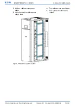


2. Bottom cable access gland
plate
3. Communication cable access
gland plate
4. Top cable access gland plate
5. Rear communication cable
conduit
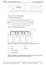
Figure 15: Cable support beams
© Eaton Corporation plc 2020. All rights reserved.
Revision: 001
Document ID: P-164000956
59 (141)
Eaton 93PM G2 UPS 50 – 360 kVA
User’s and Installation Guide