


UPS Installation Plan and Unpacking
Eaton 93E UPS (300/400 kVA, 380/400/415V) Installation and Operation Manual
3-5
3.2.2 UPS System Power Wiring Preparation
The UPS system installation must meet the following guidelines:
•
The system must be installed on a level floor suitable for computer or electronic equipment.
•
The system must be installed in a temperature and humidity controlled indoor area free of conductive
contaminants.
Failure to follow guidelines may void your warranty.
The UPS equipment operating environment must meet the weight requirements shown in Table 3-1 and the
size requirements shown in Figure 3-1. Dimensions are in millimetres (inches).
WARNING
WARNING
•
HIGH TOUCH CURRENT EARTH CONNECTION ESSENTIAL BEFORE CONNECTING SUPPLY.
As a result of the connected loads high leakage current is possible. Connection of the earth
(ground) is required for proper product operation. Do not check UPS operation by removal of
the Earth (ground) connection.
•
The UPS unit is not suitable for IT and corner-earthed power distribution systems.
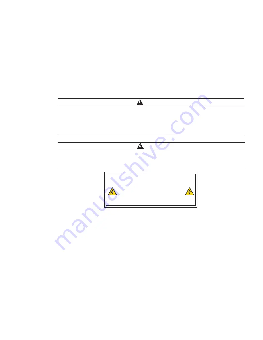
Backfeed protection is an internally fitted option on this device. If this option, or an externally fitted
backfeed contactor are not installed, the below label should be applied on all primary power
isolators installed remote from the UPS area and on external access points.
BEFORE WORKING ON THIS CIRCUIT
- ISOLATE UNINTERRUPTIBLE POWER SYSTEM (UPS)
- THEN CHECK FOR HAZARDOUS VOLTAGE BETWEEN ALL
TERMINALS INCLUDING THE PROTECTIVE EARTH
RISK OF VOLTAGE BACKFEED
自 动 反 向 馈 电 危 险 ! 线 路 施 工 前 , 请 断 开
UPS
,
确 保 所 有 端 子 之 间 包 括 保 护 地 没 有 危 险 电 压 。
•
Refer to national and local electrical codes for acceptable external wiring practices.
•
To allow for future kVA upgrades, consider installing a derated UPS using wiring and external overcurrent
protection breakers sized for a fully rated UPS.
•
For external wiring, use 90°C copper wire. Wire sizes listed in Table 3-5 are for copper wiring only. If wire is
run in an ambient temperature greater than 30°C, higher temperature wire and/or larger size wire may be
necessary. Wire sizes are based on using the specified breakers.
•
Material and labour for external wiring requirements are to be supplied by designated personnel.
•
If installing an external maintenance bypass, all feeds to the UPS including the Rectifier Input Breaker (RIB) (if
installed) must have a service disconnect independent of the maintenance bypass power path. Most
maintenance bypass solutions provide UPS input feeds derived from but isolated from the maintenance
bypass power path. If the maintenance bypass solution being installed does not provide such functionality,
DO NOT use a single feeder breaker to supply both the UPS and the maintenance bypass.
•
The bypass feed into this equipment uses four wires (three line conductors and neutral conductor), plus
grounding conductor (protective earthing conductor) . The rectifier feed into this equipment uses four wires
(three line conductors and neutral conductor), plus grounding conductor (protective earthing conductor). The
phases must be symmetrical about ground (from a Wye/Star source) for proper equipment operation.
Summary of Contents for 93E
Page 1: ...300 400 kVA 380 400 415V Installation and Operation Manual Eaton 93E UPS...
Page 2: ......
Page 4: ......
Page 19: ...Section 1 Installation...
Page 20: ......
Page 49: ...Section 2 Operation...
Page 50: ......
Page 91: ......
Page 92: ...614 08137 00...


