


UPS Operating Instructions
6-18
Eaton 93E UPS (300/400 kVA, 380/400/415V) Installation and Operation Manual
6.4
Multiple UPS Parallel Operation
Refer to the
External Battery Cabinet Installation Manual
listed in paragraph 1.8 for
EBC battery breaker location.
Start and control system wide function from UPS 1.
The breakers mentioned below are provided by customers except for UPS input
breaker(optional).
NOTE 1
NOTE 2
NOTE 3
6.4.1
Starting the Parallel UPS in Standard Normal Mode (Default Mode)
To start the UPS system:
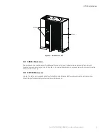
1. Unfasten the front door by lifting the latch from the bottom and turning to the right (counterclockwise) and
swing the door open (see Figure 6-1).
2. If the UPS contains an input breaker, verify that the input breaker is open.
3. If bypass input breaker is installed customer, verify that the bypass input breaker is open.
4. Close all Module Output Breakers (MOBs).
5. If input feeder circuit breaker is installed customer, close all input feeder circuit breakers.
6. If the UPS contains an input breaker, close the input breaker.
7. If bypass input breaker is installed customer, close the bypass input breaker.
8. Close the door and secure the latch.
9. Close all external battery breakers.
10. Observe the UPS control panel display becoming active, indicating logic power.
11. Verify no alarms are active.
12. Select the CONTROLS symbol on the main menu bar. The System Control screen is displayed.
13. If not already selected, select UPS on the System Control screen.
14. On the UPS System Control screen, select the LOAD OFF NORMAL command, then press the
RETURN pushbutton.
16. If requested, enter the Level 1 password. Default password is 1111.
All rectifiers and inverters turn on. The inverters continue to ramp up to full voltage.
Once all inverters reach full voltage, the UPS output contactor closes and the static switch turns off. Power
is now supplied to the critical load in Standard Normal mode. It takes approximately one minute for the
UPS to achieve Standard Normal mode.
The Normal status indicator is illuminated.
17. If output breaker is installed customer, close the output breaker.
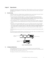
The paragraphs in this section provide operating instructions for a UPS system containing multiple UPSs.
Summary of Contents for 93E
Page 1: ...300 400 kVA 380 400 415V Installation and Operation Manual Eaton 93E UPS...
Page 2: ......
Page 4: ......
Page 19: ...Section 1 Installation...
Page 20: ......
Page 49: ...Section 2 Operation...
Page 50: ......
Page 91: ......
Page 92: ...614 08137 00...


