UPS SYSTEM INSTALLATION
Eaton 9395 UPS (450–825 kVA) Installation and Operation Manual
S
164201725 Rev 4
www.eaton.com/powerquality
4-50
12.
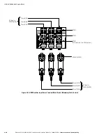
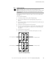
If required, install wiring from the REPO switch to the trip circuitry of the
upstream protective devices. A second contact block is provided on the REPO
switch for this function (see Figure 4‐41). The REPO switch wiring must be in
accordance with NEC Article 725 Class 2 requirements.
13.
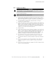
Reinstall the top internal safety shield panel and secure with the retained
hardware.
14.
Reinstall the front door removed in Step 4 and secure with the retained
hardware.
15.
Close the door and secure the latch.
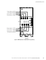
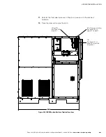
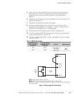
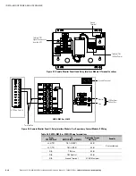
Figure 4‐43 shows the wiring connections if the normally-closed REPO contacts are
used, and Figure 4‐44 shows alternative methods of connecting a REPO switch if
using another manufacturer's switch.
3 (NO)
UPS TB1
REPO
Switch
(NC)
Twisted
Wires
1 (NC)
2 (Return)
4 (Return)
NOTE
REPO switch rating is 24 Vdc, 1A minimum.
NOTE
T
he REPO switch must be a latching-type switch not tied to any other circuits.
NOTE
REPO normally-open and normally-closed return terminals are separated on the terminal board but are
electrically in common.
1
2
Figure 4‐43. Normally‐Closed REPO Switch Wiring

