background image

24

Eaton 9355 Parallel UPS (10/15 kVA) User's Guide 164201601—Rev E0

17. Replace the UPS wiring access cover and conduit landing plate.

18. Repeat

Step 12

through

Step 17

for each UPS.

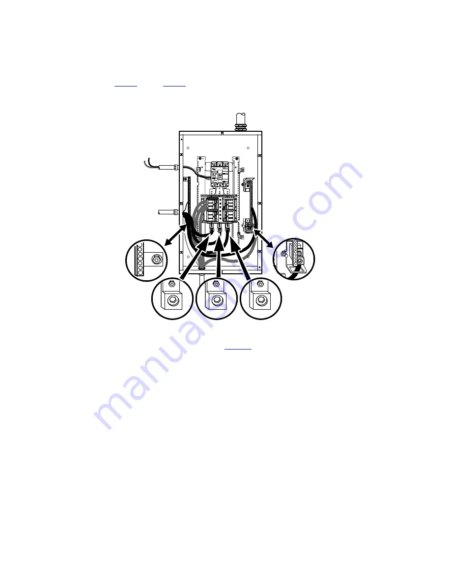
Figure 17. Version 1 Load Connections

Ground

Line 1

Neutral

Line 2

Line 3

Maintenance Bypass

Wiring to UPS TB2

19. Wire the AC input to the bypass breaker (see

Figure 18

).

UPS System Installation

Summary of Contents for 9355 Series

Page 1: ...p n 164201601 Revision E0 10 15 kVA User s Guide Eaton 9355 Parallel UPS ...

Page 2: ...e pursuant to part 15 of the FCC Rules These limits are designed to provide reasonable protection against harmful interference when the equipment is operated in a commercial environment This equipment generates uses and can radiate radio frequency energy and if not installed and used in accordance with the instruction manual may cause harmful interference to radio communications Operation of this ...

Page 3: ...lid or unenforceable the remaining provisions of this Agreement will remain in full force 5 5 Waiver The waiver by either party of any default or breach of this Agreement will not constitute a waiver of any other or subsequent default or breach Failure to enforce or delay in enforcing any provision of this Agreement will not constitute a waiver of any rights under any provisions of this Agreement ...

Page 4: ......

Page 5: ...n ng g 9 9 3 1 Creating an Installation Plan 9 3 2 Preparing the Site 9 3 2 1 Environmental and Installation Considerations 9 3 3 Parallel UPS System Power Wiring Preparation 11 3 4 Inspecting the Equipment 12 4 4 U UP PS S S Sy ys st te em m I In ns st ta alllla at tiio on n 1 13 3 4 1 Preliminary Installation Information 13 4 2 Unloading the UPS Cabinet from the Pallet 13 4 2 1 Three High Cabine...

Page 6: ...uring the UPS for EBMs 54 6 4 Parallel System Shutdown 55 6 5 Individual UPS Shutdown 55 6 6 Restarting the Parallel System 56 6 7 Parallel Bypass Operation 56 7 7 T Tr ro ou ub blle es sh ho oo ot tiin ng g 5 59 9 7 1 Typical Alarms and Conditions 59 7 2 Silencing the Alarm 60 8 8 W Wa ar rr ra an nt ty y 6 61 1 Table of Contents ...

Page 7: ...rsion 1 Bypass AC Input Wiring 25 Figure 19 Version 2 Parallel Tie Cabinet Front Door and Cover 26 Figure 20 Version 2 Parallel Tie Cabinet Front Cover Open 27 Figure 21 Version 2 Parallel Tie Cabinet Internal Cover 28 Figure 22 Version 2 Parallel Tie Cabinet Bypass Breaker 29 Figure 23 UPS Rear View 3 High Shown 30 Figure 24 UPS Terminal Block 3 High Shown 31 Figure 25 Version 2 Tie Cabinet UPS O...

Page 8: ... 41 Version 1 Tie Cabinet Parallel UPS Schematic 46 Figure 42 Version 2 Tie Cabinet Parallel Wiring Diagram without Maintenance Isolation Switch MIS 47 Figure 43 Version 2 Bypass Cabinet Bypass Wiring Diagram with MIS 47 Figure 44 Version 2 Tie Cabinet Parallel UPS Schematic 48 Figure 45 Eaton 9355 UPS Control Panel 49 List of Figures ...

Page 9: ... es s Table 1 Air Conditioning or Ventilation Requirements During Full Load Operation 10 Table 2 UPS Cabinet Weights 10 Table 3 UPS Cabinet Clearances 11 Table 4 Eaton 9355 10 15 kVA Parallel UPS Recommended Terminal Block Wiring 12 Table 5 Menu Map for Display Functions 50 Table 6 User Settings 51 ...

Page 10: ...x Eaton 9355 Parallel UPS 10 15 kVA User s Guide 164201601 Rev E0 List of Tables ...

Page 11: ...BM IMPORTANT Startup and operational checks must be performed by an authorized Eaton Customer Service Engineer or the warranty terms specified on the product s resources page become void See Chapter 8 Warranty for details This service is offered as part of the sales contract for the UPS Contact an Eaton service representative in advance a minimum two week notice is required to reserve a preferred ...

Page 12: ...tem options and accessories being installed dictate which parts of this manual should be read At a minimum Chapter 1 Introduction through Chapter 4 UPS System Installation and Chapter 6 UPS Operating Instructions should be examined Read through each procedure before beginning the work Perform only those procedures that apply to the UPS system being installed or operated 1 1 2 2 C Co on nv ve en nt...

Page 13: ... the trash For proper disposal contact your local recycling reuse or hazardous waste center ON Indicates that the switch is in the ON position OFF Indicates that the switch is in the OFF position PHASE The word phase 1 1 4 4 F Fo or r M Mo or re e I In nf fo or rm ma at tiio on n Refer to the Eaton 9355 UPS 10 15 kVA User s Guide for the following additional information Installation instructions i...

Page 14: ...ll other countries Call your local service representative Please have the following information ready when you call for service Model number Serial number Firmware version number Date of failure or problem Symptoms of failure or problem Customer return address and contact information Please use the following e mail address for manual comments suggestions or to report an error in this manual E ESSD...

Page 15: ...ire or electric shock install this UPS in a temperature and humidity controlled indoor environment free of conductive contaminants Ambient temperature must not exceed 40 C 104 F Do not operate near water or excessive humidity 95 maximum To reduce the risk of fire connect only to a circuit provided with 100 amperes maximum branch circuit overcurrent protection in accordance with the National Electr...

Page 16: ... pas branché sur le secteur Pour réduire les risques d incendie et de décharge électrique installer l onduleur uniquement à l intérieur dans un lieu dépourvu de matériaux conducteurs où la température et l humidité ambiantes sont contrôlées La température ambiante ne doit pas dépasser 40 C Ne pas utiliser à proximité d eau ou dans une atmosphère excessivement humide 95 maximum La protection contre...

Page 17: ...nsmitir corriente eléctrica aun cuando el SIE no esté conectado a un suministro de corriente alterna c a Para reducir el riesgo de incendio o de choque eléctrico instale este SIE en un lugar cubierto con temperatura y humedad controladas libre de contaminantes conductores La temperatura ambiente no debe exceder los 40 C No trabaje cerca del agua o con humedad excesiva 95 máximo La protección contr...

Page 18: ...8 Eaton 9355 Parallel UPS 10 15 kVA User s Guide 164201601 Rev E0 Safety Warnings ...

Page 19: ...s specified 3 3 2 2 1 1 E En nv viir ro on nm me en nt ta all a an nd d I In ns st ta alllla at tiio on n C Co on ns siid de er ra at tiio on ns s The UPS system installation must meet the following guidelines The system must be installed on a level floor suitable for computer or electronic equipment The system must be operated at an altitude no higher than 1500m 5000 ft without derating For addit...

Page 20: ...mbient Temperature Range 5 40 C 41 104 F Recommended Operating Range 5 40 C 41 104 F Maximum Relative Humidity 5 95 noncondensing CAUTION If battery systems are located in the same room as the UPS the battery manufacturer s environmental requirements should be followed if they are more stringent than the UPS requirements Operating temperatures above the recommended range will result in decreased b...

Page 21: ...tand the following notes while planning and performing the installation WARNING As a result of the connected loads high leakage current is possible Connection to earth ground is required for safety and proper product operation Do not check UPS operation by any action that includes removal of the earth ground connection with loads attached Refer to national and local electrical codes for acceptable...

Page 22: ...three phase conductors must be run in the same conduit Neutral and ground must be run in the same conduit as the phase conductors 3 Conduit is sized to accommodate one neutral conductor the same size as the phase conductor and one 8 AWG ground conductor If two neutral conductors or an oversized neutral conductor are to be installed check the size of the conduit needed to accommodate the extra wire...

Page 23: ...e required for ventilation place them in front of the UPS 4 4 2 2 U Un nllo oa ad diin ng g t th he e U UP PS S C Ca ab biin ne et t f fr ro om m t th he e P Pa alllle et t The following tools are required for unloading the cabinet s 15 mm wrench or socket 7 mm nut driver or socket CAUTION The UPS and EBM are heavy see Table 2 Unloading the cabinets requires at least two people to safely remove th...

Page 24: ...nd hardware for later re assembly onto the cabinet 4 Remove the front cover from the bottom cabinet to access the front shipping bracket Press and release the handle latch at the bottom of the cover and then lift the cover up and off the cabinet 5 Remove the three M10 bolts securing the rear shipping pad to the pallet and remove the shipping pad NOTE Hold the back of the cabinet so that the bolts ...

Page 25: ...ont cover removed in Step 4 Hang the top edge of the cover on the cabinet first then lower the bottom edge and snap into place NOTE Support the front and back of the cabinet when rolling it off the pallet to prevent tipping 8 Slowly roll the cabinet toward the rear of the pallet Once the pallet tilts continue rolling the cabinet down the pallet until the cabinet touches the floor see Figure 4 If n...

Page 26: ... Removing the Pallet 10 Roll the cabinet to the desired location 4 4 2 2 2 2 T Tw wo o H Hiig gh h U UP PS S C Ca ab biin ne et ts s To remove a two high UPS from the shipping pallet 1 Remove the M10 bolt securing the vertical bracket to the pallet see Figure 6 2 Remove and retain the three M4 screws securing the vertical bracket to the UPS Remove the vertical bracket UPS System Installation ...

Page 27: ...ing the leveling feet to the pallet see Figure 7 5 Repeat Step 1 through Step 4 to remove the vertical bracket on the other side 6 Remove the front cover from the bottom cabinet to access the front shipping bracket Press and release the handle latch at the bottom of the cover and then lift the cover up and off the cabinet 7 Remove the three M10 bolts securing the rear shipping pad to the pallet an...

Page 28: ...s M10 Bolts 9 Reinstall the front cover removed in Step 6 Hang the top edge of the cover on the cabinet first then lower the bottom edge and snap into place NOTE Support the front and back of the cabinet when rolling it off the pallet to prevent tipping 10 Slowly roll the cabinet toward the rear of the pallet Once the pallet tilts continue rolling the cabinet down the pallet until the cabinet touc...

Page 29: ...ne of the following installation options according to your UPS configuration To install the Version 1 Tie Cabinet see paragraph 4 3 1 Version 1 Tie Cabinet Parallel Installation To install the Version 2 Tie Cabinet see paragraph 4 3 2 Version 2 Tie Cabinet Parallel Installation 4 4 3 3 1 1 V Ve er rs siio on n 1 1 T Tiie e C Ca ab biin ne et t P Pa ar ra alllle ell I In ns st ta alllla at tiio on ...

Page 30: ...n device must be incorporated in the input wiring Compare the circuit breaker ratings to the ones in Table 4 NOTE To accommodate the feature of easy system expandability it is recommended that initial installation of the Eaton 9355 UPS contain wiring to support the maximum capacity of the UPS cabinet 3 Switch off utility power to the distribution point where the parallel tie cabinet and UPSs will ...

Page 31: ...eenlee punch or similar device 8 Verify that the parallel bypass breaker is in the OFF position see Figure 13 9 Mount the parallel tie cabinet to the wall and install the conduit Figure 13 Version 1 Parallel Bypass Breaker 10 Verify that each UPS battery circuit breaker is in the OFF position see Figure 14 11 From each UPS remove the UPS wiring access cover and one of the conduit landing plates an...

Page 32: ...r UPS Wiring Access Cover Conduit Landing Plates 13 Hardwire the UPS input terminations See Table 4 for specifications and Figure 15 for a detailed view of the UPS terminal block NOTE 1 Input neutral must be wired for proper operation Failure to connect an input neutral will void the warranty If the optional input transformer is installed an input neutral is not required NOTE 2 The Eaton 9355 UPS ...

Page 33: ...lel Tie Cabinet Wiring Neutral Line 1 Line 2 Line 3 Ground 15 Hardwire the load to the parallel tie cabinet see Figure 17 16 Wire the maintenance bypass contacts and terminate to the maintenance bypass wires in the parallel tie cabinet see Figure 15 Connect the black and the red wire to TB2 on the UPS Cap the blue wire NOTE The maintenance bypass contacts are normally open To ensure proper bypass ...

Page 34: ...S wiring access cover and conduit landing plate 18 Repeat Step 12 through Step 17 for each UPS Figure 17 Version 1 Load Connections Ground Line 1 Neutral Line 2 Line 3 Maintenance Bypass Wiring to UPS TB2 19 Wire the AC input to the bypass breaker see Figure 18 UPS System Installation ...

Page 35: ...PS has the following power connections 3 phase L1 L2 and L3 neutral and ground connection for rectifier bypass input 3 phase L1 L2 and L3 neutral and ground connection for load output The nominal input output voltages are 120 208 or 127 220 Vac Output overcurrent protection and disconnect switch must be provided by others WARNING Only qualified service personnel such as a licensed electrician shou...

Page 36: ...lity power to the distribution point where the parallel tie cabinet and UPSs will be connected Be absolutely sure there is no power 4 Determine your equipment s grounding requirements according to your local electrical code 5 Unfasten the bypass cabinet front door latch and swing the door open see Figure 19 6 Follow the instructions on the inside of the door to open or remove the front cover see F...

Page 37: ... 10 15 kVA User s Guide 164201601 Rev E0 27 Figure 20 Version 2 Parallel Tie Cabinet Front Cover Open Internal Cover Front Cover 7 Remove the internal cover to gain access to the breakers see Figure 21 UPS System Installation ...

Page 38: ...ernal Cover 8 Punch holes for the conduit AC input UPS output load connection and maintenance bypass contact wires using a Greenlee punch or similar device 9 Verify that the parallel bypass breaker is in the OFF position see Figure 22 10 Mount the parallel tie cabinet to the wall and install the conduit UPS System Installation ...

Page 39: ...Verify that each UPS battery circuit breaker is in the OFF position see Figure 23 12 From each UPS remove the UPS wiring access cover and one of the conduit landing plates and retain 13 Punch two holes in the conduit landing plate for the input and output conduit using a Greenlee punch or similar device UPS System Installation ...

Page 40: ...the UPS input terminations See Table 4 for specifications and Figure 24 for a detailed view of the UPS terminal block NOTE 1 Input neutral must be wired for proper operation Failure to connect an input neutral will void the warranty If the optional input transformer is installed an input neutral is not required NOTE 2 The Eaton 9355 UPS is a single feed UPS only UPS System Installation ...

Page 41: ...kVA User s Guide 164201601 Rev E0 31 Figure 24 UPS Terminal Block 3 High Shown Ground Maintenance Bypass Contacts TB2 15 Hardwire the output terminations from the UPS to the parallel tie cabinet see Figure 25 UPS System Installation ...

Page 42: ...ce bypass contacts and terminate to the maintenance bypass wires in the parallel tie cabinet see Figure 24 Connect the black and the red wires from the terminal block on the Tie Cabinet to TB2 on the UPS NOTE The maintenance bypass contacts are normally open To ensure proper bypass operation DO NOT use the blue wire it is normally closed 18 Replace the UPS wiring access cover and conduit landing p...

Page 43: ...User s Guide 164201601 Rev E0 33 Figure 26 Version 2 Tie Cabinet Load Connections Line 1 Line 2 Line 3 Ground Neutral Maintenance Bypass Wiring to UPS TB2 20 Wire the AC input to the bypass breaker see Figure 27 UPS System Installation ...

Page 44: ...ed to paragraph 4 3 3 Installing Options to continue the installation process 4 4 3 3 3 3 I In ns st ta alllliin ng g O Op pt tiio on ns s This section describes the Powerware Hot Sync CAN Bridge Card For other options such as additional X Slot cards LanSafe Power Management Software remote emergency power off REPO relay output contacts or programmable signal inputs refer to the Eaton 9355 UPS 10 ...

Page 45: ... ot t S Sy yn nc c C CA AN N B Br riid dg ge e C Ca ar rd d The Powerware Hot Sync CAN Bridge Card shown in Figure 29 can be installed to provide connectivity for operational mode control and metering of a parallel system at any UPS in the system Figure 29 Powerware Hot Sync CAN Bridge Card Plug In Terminal Block To install the Powerware Hot Sync CAN Bridge Card 1 Remove the front covers of all ca...

Page 46: ...cards together 4 Wire the factory installed pull chain wiring to Signal Input 2 on each UPS and daisy chain the wiring to each UPS as shown in Figure 31 Verify correct polarity Connect COM Pin 4 to Signal Input 2 Pin 1 on each UPS Connect NC Pin 3 to Signal Input 2 Pin 2 on each UPS CAUTION If polarity or wiring is not correct the parallel system does not operate normally For example when shutting...

Page 47: ... 1 7 6 5 4 3 2 NO COM NC ALM RTN ALARM J3 J5 1 2 1 2 1 2 1 2 4 S P U 3 S P U 2 S P U 1 S P U 5 On the bottom cover and also the middle cover if 3 high remove a knockout tab in the top edge of the cover for each cable With wire cutters cut either side of the tab and twist down to remove the tab see Figure 32 UPS System Installation ...

Page 48: ...p edge of the cover on the cabinet first then lower the bottom edge and snap into place Verify that the cables fit in the access holes in the covers Figure 33 Reinstalling the Front Covers 8 Proceed to paragraph 4 3 4 Stabilizing the Cabinet to complete the parallel UPS installation NOTE After UPS startup ensure maximum battery runtime by configuring the UPS for the correct number of EBMs see para...

Page 49: ...using the retained hardware from the shipping pallet according to the cabinet configuration For one cabinet see Figure 35 For two cabinets see Figure 36 For three cabinets see Figure 37 NOTE No more than three cabinets can be attached together For four cabinets use two of the two cabinet installations For five cabinets use one three cabinet and one two cabinet installation 3 Use the holes and slot...

Page 50: ... Eaton 9355 Parallel UPS 10 15 kVA User s Guide 164201601 Rev E0 Figure 35 Stabilizing Bracket with One Cabinet M4 Screws Figure 36 Stabilizing Bracket with Two Cabinets M4 Screws UPS System Installation ...

Page 51: ... optional for 2 high cabinets NOTE 3 In a parallel system each UPS should have the same number of Extended Battery Modules EBMs to ensure equivalent runtimes To install the optional EBM 1 Position the EBM adjacent to the next cabinet 2 Verify that all battery circuit breakers are in the OFF position see Figure 38 3 Remove the two ground straps from the EBM rear panel 4 Install one ground strap bet...

Page 52: ...h at the bottom of the cover and then lift the cover up and off the cabinet 9 Install the remaining ground straps between each cabinet see Figure 39 10 Reinstall the top front covers removed in Step 8 Hang the top edge of the cover on the cabinet first then lower the bottom edge and snap into place 11 Proceed to Chapter 6 Operation to start up the UPS NOTE After UPS startup ensure maximum battery ...

Page 53: ...Eaton 9355 Parallel UPS 10 15 kVA User s Guide 164201601 Rev E0 43 Figure 39 Front Ground Strap Installation 2 High Cabinets Shown Front Ground Strap UPS System Installation ...

Page 54: ...44 Eaton 9355 Parallel UPS 10 15 kVA User s Guide 164201601 Rev E0 UPS System Installation ...

Page 55: ...a ag gr ra am m S Sc ch he em ma at tiic cs s Figure 40 Version 1 Tie Cabinet Parallel Wiring Diagram From UPS 4 Output From UPS 3 Output From UPS 2 Output Red Wire open when breaker is open Bypass Input Black Wire common From UPS 1 Output 225A 80A 4X LOAD Blue Wire closed when breaker is open 225A Breaker Auxiliary Contacts ...

Page 56: ...46 Eaton 9355 Parallel UPS 10 15 kVA User s Guide 164201601 Rev E0 Figure 41 Version 1 Tie Cabinet Parallel UPS Schematic UPS Wiring Diagram Schematics ...

Page 57: ...en Bypass Input Black Wire common From UPS 1 Output 225A 80A 4X LOAD Blue Wire closed when breaker is open 225A Breaker Auxiliary Contacts Figure 43 Version 2 Bypass Cabinet Bypass Wiring Diagram with MIS Red Wires open when breaker is open Black Wires common Blue Wires closed when breaker is open 225A Breaker Auxiliary Contacts Not Used Not Used Not Used Bypass Input From UPS 1 Output 225A 110A 4...

Page 58: ...48 Eaton 9355 Parallel UPS 10 15 kVA User s Guide 164201601 Rev E0 Figure 44 Version 2 Tie Cabinet Parallel UPS Schematic UPS Wiring Diagram Schematics ...

Page 59: ...splay Functions As the default or after 15 minutes of inactivity the LCD displays the selectable startup screen The default is the Eaton logo and can be changed to the Mimic screen in the User Settings menu The backlit LCD automatically dims after a long period of inactivity Press any button to restore the screen Use the two middle buttons and to scroll through the menu Yellow On The UPS is in Bat...

Page 60: ...automatically dims after a long period of inactivity Press store the screen ddle buttons and to scroll through the menu the button to enter a submenu Press the button on Press the ESC button to cancel or return to the button to select an option Press the Eaton 9355 Parallel UPS 10 15 kVA User s Guide S 164201601 Rev B 56 Display Functions As the default or after 15 minutes of inactivity the LCD di...

Page 61: ...ired to the CAN Bridge Card For more information refer to Programmable Signal Inputs in the Eaton 9355 UPS 10 15 kVA User s Guide empty Serial Port Config Port X Slot 1 X Slot 2 Serv Speed 19200 9600 2400 1200 19200 Modem Config Modem Installation Not Installed Set Modem Call Events Event 0 Call modem no Set Modem Init String ATZ0 Set Modem Call Command None Set Modem Communication Password None S...

Page 62: ... disabled 0s Control Commands from X Slot1 Allowed Disabled Allowed Control Commands from X Slot2 Serv Allowed Disabled Allowed X Slot Signal Input Activation Delay 0 through 65 seconds 5s Input signal delayed shutdown delay 1 through 65535 seconds 120s Site Wiring Fault Notice Enabled Disabled Enabled Reset Custom Event Settings 0 through 32 Total 0 32 Auto Output Configuration Enabled Disabled E...

Page 63: ... the ON position The indicator stops flashing on each UPS 6 Configure the UPS for parallel operation through the front panel Press any button on the front panel display to activate the menu options Using the button scroll to the Settings menu and then press the button twice to select the User Settings menu Use the button to scroll to the Parallel Operation Mode option and press the button to enter...

Page 64: ...nguage Press and hold the first button on the left for approximately five seconds to select the language menu This action is possible from any LCD menu screen Display Functions As the default or after 15 minutes of inactivity the LCD displays the selectable startup screen The default is the Eaton logo and can be changed to the Mimic screen in the User Settings menu The backlit LCD automatically di...

Page 65: ...the button to select an option Press the ESC button to cancel or return to the previous menu button until the Eaton logo or Mimic screen appears 6 6 4 4 P Pa ar ra alllle ell S Sy ys st te em m S Sh hu ut td do ow wn n To remove power to the parallel UPS system output 1 Press any button on the front panel display to activate the menu options 2 Press the button on the front panel display and then p...

Page 66: ...formation Changing the Language Press and hold the first button on the left for to select the language menu This action is p screen Display Functions As the default or after 15 minutes of inactivi selectable startup screen The default is the changed to the Mimic screen in the User Se The backlit LCD automatically dims after a lo any button to restore the screen Use the two middle buttons and to sc...

Page 67: ...Maintenance Bypass 3 Verify voltage is present on the UPS output by checking that an output voltage reading present on the front panel LCD display The load is now powered by utility power indicator illuminates indicating the UPS system is operating in Bypass mode The display indicates On Manual Maintenance Bypass 3 Verify voltage is present on the UPS output by checking that an output voltage read...

Page 68: ...58 Eaton 9355 Parallel UPS 10 15 kVA User s Guide 164201601 Rev E0 Operation ...

Page 69: ... not turn on automatically Yellow On The UPS is in Battery mode Yellow On The UPS is in Bypass mode Red On The UPS has an active alarm Flashing There is a new UPS alarm condition See Troubleshooting on page 67 for additional information Changing the Language Press and hold the first button on the left for approximately five seconds to select the language menu This action is possible from any LCD m...

Page 70: ...ormation Changing the Language Press and hold the first button on the left for approximately five seconds to select the language menu This action is possible from any LCD menu screen Display Functions As the default or after 15 minutes of inactivity the LCD displays the selectable startup screen The default is the Eaton logo and can be changed to the Mimic screen in the User Settings menu The back...

Page 71: ...ap pt te er r 8 8 W Wa ar rr ra an nt ty y For warranty information please refer to the Resources link on our website www eaton com 9355 EQUIPMENT REGISTRATION Please visit www eaton com pq register to register your new Eaton UPS Eaton UPS Accessory Model Number Serial Number ...

Page 72: ...164201601E0 164201601 E0 ...

Reviews: