
IOM 2596 Cast 10”–16” | Fabricated 10”-36” 10/2011
REV A.
Page 2 of 15
Eaton Filtration, LLC, 44 Apple Street, Tinton Falls, NJ 07724 | www.eaton.com/filtration | Phone: 732-212-4700
Installation, Operation & Maintenance Manual
Model 2596 Self-Cleaning Strainer
Cast 10” to 16” and Fabricated 10” to 36”
RECEIVING,
HANDLING,
AND
INSPECTION
Prior to shipment, strainers are coated internally and on
external machined surfaces to protect against rust. All openings
are covered and the motor-reducer unit wrapped with plastic
and secured with waterproof tape. The motor is packed
separately.
1.
Unpack the strainer and inspect for damage occurring
during transit. Report damage to the carrier. If the strainer
is not installed immediately, see “Storage” instructions.
2.
Remove preservatives with solvent-dampened cloths.
Exercise care when using solvent.
3.
Verify the rated pressure and temperature on the strainer
nameplate is not less than the maximum pressure and
temperature of the system.
4.
The rated pressure shown on the nameplate is the
maximum pressure, including shock, at which the strainer
may be operated
5.
Check to be sure the available electrical power matches
the voltage, phase and cycle requirements of the strainer
motor and automatic control panel.
6.
Remove flange and thread protectors. Check for and
remove any foreign or loose materials such as blocking,
desiccant bags, etc. that could be carried downstream
when fluid is introduced into the strainer.
STORAGE
Whenever possible, store strainers indoors in a clean, dry
environment. Replace all protective wrappings, flange
protectors, plugs, etc. which may have been removed during
receiving inspection.
Outdoor storage, if unavoidable, requires special treatment.
a.
Place a bag of silica-gel or similar desiccant in each strainer
to absorb moisture (attach to inside of flange protectors).
b.
Reapply rust preventative to any machined surface which
became exposed due to handling and/or receiving
inspection.
c.
Make sure all openings are covered. Seal flange protectors
with waterproof tape.
d.
Wrap motor-reducer unit with plastic and secure with
tape. Permit air circulation or provide adequate desiccant
for moisture control.
e.
Protect the entire strainer with heavy polyethylene wrap
and seal with waterproof tape.
CAUTION:
Before strainers are put into operation
after storage be sure to remove all desiccants,
protective bags, caps, plugs, etc. Inspect gasketing
and shaft seals for possible deterioration and
replace as required. Inspect oil level in reducer and check
lubricant for accumulated condensation.
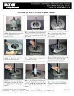
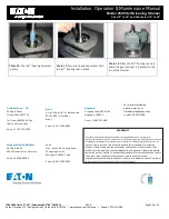
INSTALLATION
Position the strainer in the line so that the fluid enters the
connection marked inlet
.
CAUTION:
Any alteration to the piping between
the pump and the strainer could affect the
performance of the unit. Lift strainer with slings
under the inlet and outlet connection.
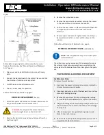
Be sure sufficient headroom is provided for easy removal of the
internal parts. Refer to sales drawing for removal clearance.
NOTE
: Clearance for rigging equipment must also
be considered.
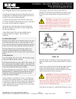
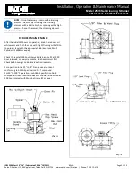
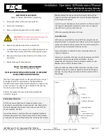
Support the strainer in the line as follows:
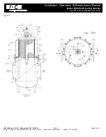
Both cast and fabricated strainers are provided with mounting
feet. The footpads are drilled to accommodate the use of
anchor bolts. Place the strainer in the line on concrete or steel
mounts. Do not support the strainer or the piping coming to
and from the strainer by the line flanges and flange bolting. See
Fig 1(cast) or Fig 5 (fabricated) and sales drawing.
Connect the strainer to the line. Use the same type flange
faces. For example, do not bolt raised face flanges to iron flat
face flanges. Iron flanges must be flat face with full face
gaskets.
Strainers are subject to fact-to-face variations due to machining
and fabrication tolerances. Prefabricated piping systems must
allow adjustment at the strainer connections.


