21
OPERATING
SEQUENCE
The Easy Radiant gas burner is a very simple device. The normal sequence of events
during ignition and operation of the burner is as follows:
1.
The heater is energized by means of a thermostat or switch.
2.
When 24 volts is applied to the module, the module will energize the blower and
close the airswitch.
3.
The current flows and energizes the igniter and reaches ignition temperature. No
gas flows until the valve is energized and opened.
4.
Air pressure generated by the blower will cause the normally open combustion
pressure switch to close. The combustion pressure switch is set to allow the
normal rate of combustion air to flow into the combustion chamber. Any
restriction or blockage will cause the pressure switch to open and shut down the
entire system.
5.
The current passes through the blocked flue pressure switch, which is normally
closed. Any blockage or restriction will cause the pressure switch to open and
shut down the entire system.
6.
After 17 seconds, the valve is energized and opened. Gas flows through the
burner and is ignited.
7.
The power is removed from the igniter. The flame sensor is utilized. As long as a
flame is present, the valve is held open. If the flame is lost, the control acts to
close the valve within one second and a new trial sequence to start up is initiated.
8.
If ignition is not achieved, or flame is not sensed, then the control closes, the gas
valve, and attempts ignition a second time, and if necessary a third time. If
ignition is not achieved after the third try, the control goes into lockout for 30
minutes and power must be interrupted before trying again. At this point it is
suggested that an authorized service person be contacted to inspect and test the
controls.
9.
The heater should continue to function until power is interrupted either by the
thermostat being satisfied or manually disconnected.
NATURAL
GAS
AND
LIQUID
PROPANE
CONVERSION:
1.
Turn off gas supply at the appliance service valve.
2.
Remove regulator cap screw and pressure regulator adjusting screw
3.
Replace the existing spring with replacement spring.
4.
Re-install regulator cap screw and pressure regulator adjusting screw.
5.
Replace gas orifice with the one provided by the manufacturer.
6.
Check the regulator setting using a manometer.
7.
Mount the conversion label on the gas control
8.
Mount the new rating label on the heaters
Summary of Contents for Middleman EZM-100-50
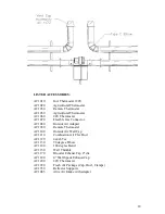
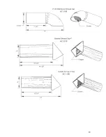
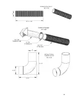
Page 17: ...17 VENTING OPTIONS...
Page 19: ...19...
Page 20: ...20...
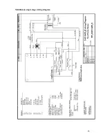
Page 25: ...25 Middleman single stage wiring diagram...
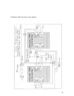
Page 26: ...26 Middleman LTH dual input wiring diagram...
Page 28: ...28...


