background image

16


Eastwood Technical Assistance: 800.343.9353  >>  [email protected]

VACUUM MAINTENANCE

The Vacuum is designed to keep the dust level in the cabinet low for maxi-
mum visibility while blasting. As the Blaster is operated, make-up air enters 
the vent at the left front Hopper panel, circulates through the cabinet and is 
drawn though the outlet baffle at the upper rear panel.

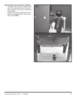
•  After every 10 minutes of blasting, operate the Filter Plunger at the 

side of the Vacuum Housing 

(FIG 27)

.  

To do so: Strike the plunger sharply with the side or palm of the 
hand. This will strike the Filter allowing any caked accumulation of 
media dust to fall into the bottom hopper.  As the Filter is repeatedly 
struck, the hopper will fill with media dust and must be emptied. To 
do so: unlatch the Clasp on the conical vacuum hopper base and 
allow the dust to discharge into a container.

•  If it becomes apparent that the vacuum is failing to clear the dust from the cabinet while dusting, the Filter must be cleaned. To do so: 
  -  Turn off unit and unplug the power supply cord.
  -  Unlatch the Clasps on the sides of the Vacuum/Filter Assembly and pull the Motor & Filter out of the top of the Housing and set it upside down  

  with the Filter base upward.

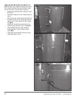
  -  Loosen and remove the Filter Retaining Wingnut and Washer 

(FIG 28)

.

  -  Pull the Filter free of the Motor Unit.
  -  Clean dust from the rubber seal.
  -  Using a suitable blow gun and compressed air source, blow air through the Filter from the inside out.
  -  When done, replace Filter and secure it with the Filter Retaining Washer and Wingnut.
  -  Replace the Motor & Filter assembly back into the Housing and latch the Clasps securely.
  -  Reconnect the Power Supply Cord.

  The fine dust accumulated by this unit is a Health Hazard!  Avoid breathing dust produced by handling the Filter. Always wear ap-

propriate NIOSH approved breathing apparatus when cleaning, emptying or maintaining the unit and use in a well-ventilated area.

  Always dispose of exhausted media properly following all local hazardous material disposal regulations. Levels of hazardous ma-

terials such as lead, zinc chromate, etc. may be present in coatings being removed. Additional precautions may be required in the 
presence of these substances.

FIG. 27

FIG. 28

Summary of Contents for B100

Page 1: ...ABRASIVE MEDIA BLAST CABINET B100 INSTRUCTIONS Item 21301...

Page 2: ...Peel Off Lamp Protection Panel Shields 3 Spare Nozzles 1 Roll Teflon Tape HARDWARE 35 M6 x 12mm Pan Head Screws 35 M6 Self Locking Nuts REQUIRED FOR USE The inlet air supply must have a moisture separ...

Page 3: ...d personal injury DO NOT exceed 90 psi 6 3 bar of tool inlet air pressure HEALTH AND INJURY HAZARDS The Eastwood Abrasive Media Blast Cabinet consists of large heavy metal components which can cause p...

Page 4: ...oosen the six M6 screws holding it in place at the underside of the roof of the Cabinet Carefully withdraw the Light Fixture D and the Glass Lamp Protection Panel F Set the Light Fixture D and the Gla...

Page 5: ...accessible at this point Pass 2 M6 x 12mm Screws through holes from the outside add M6 Nuts FIG 4 Tighten securely Place another Leg B over the front corner of the Cabinet A aligning 4 sets of holes N...

Page 6: ...ved hands along rubber seal inside the open light fixture slot at the top of the Cabinet and lift slowly and steadily to upright position DO NOT allow legs to collapse Align all holes in Legs and Cabi...

Page 7: ...O TOP OF CABINET LOCATION D F TO A Place the Light Fixture on its back and remove the Florescent Tubes E from packaging Align contact pins at the end of Fluorescent Tubes with the spring loaded lamp r...

Page 8: ...FIG 11 Place the Light Fixture D with Switch facing forward over the Glass Panel F and align the 3 mounting slots per side with the 6 holes in the cabinet top FIG 12 Add the 6 previously removed Light...

Page 9: ...om right of the Hopper section of the Cabinet A Align the mount ing holes of the bracket with the 2 holes in the right front Hopper panel and secure it with 2 M6 Screws and Nuts FIG 14 Slip the end of...

Page 10: ...BINET FLOOR H Let the Abrasive Blasting Gun and Hose G hang out of the right front corner of the Cabinet Set the Perforated Cabinet Floor H with angled cut off corner toward right front of cabinet and...

Page 11: ...r Valve in place on the upper front face of the Left Leg align the mounting holes of the bracket with the 2 holes in the Leg and secure it with 2 M6 Screws and Nuts FIG 18 Slip the end of the Orange A...

Page 12: ...the Motor Filter out of the top of the Housing and set it aside With the assistance of a helper align the mounting holes of the brackets with the 4 holes at the upper back wall of the Cabinet Secure...

Page 13: ...pen the front loading Lid place object to be blasted on the Perforated Floor Panel Open the Air Inlet Valve on the Regulator Air Inlet Assembly FIG 24 The included Regulator is used to limit incoming...

Page 14: ...or alcohol Peel off adhesive protective strips and apply replacement shield to interior glass surface Press on adhesive areas to ensure an abrasive proof seal CERAMIC NOZZLE REPLACEMENT Replace the N...

Page 15: ...10 of the Perforated Floor support flanges DO NOT OVERFILL Overfilling will degrade performance DO NOT USE SAND IN THIS BLAST CABINET NOTE for best results and to avoid nozzle clogging do not use med...

Page 16: ...G 28 Pull the Filter free of the Motor Unit Clean dust from the rubber seal Using a suitable blow gun and compressed air source blow air through the Filter from the inside out When done replace Filter...

Page 17: ...To order parts and supplies 800 343 9353 eastwood com 17 A B B B B C D E F Assembled G H J K Assembled Included with A Assembled Included with A J...

Page 18: ...18 Eastwood Technical Assistance 800 343 9353 tech eastwood com NOTES...

Page 19: ...r supply Debris or Blasting Residue in Gun Nozzle Clean out gun nozzle then drain and sift blast media to remove debris before re use Excessive Media in Hopper For best results operate blaster with th...

Page 20: ...2018 Walnut Shell Media 12 20 Grit 13779 Ground Glass Media 40 70 Grit 13772 Glass Bead Media 100 170 Grit 22023 Glass Bead Media 70 100 Grit 11806 Soda Media 10 lbs 21135 Replacement Nozzles 2pc Copy...

Reviews: