22
16. Disassembly of the foot rest actuator
①
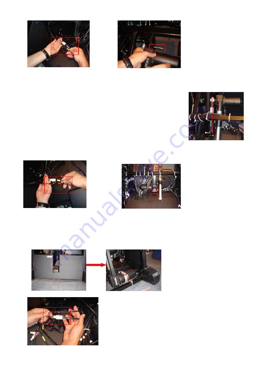
Disassemble the backrest from the chair, then find the reclining actuator
②
Along the connecting wires of the reclining actuator to find the
2 connectors, then disconnect them.
③
Raise the foot rest to the extreme position, then find each end
of the actuator is fixing on the U stay fork. There are two plastic bush
rings in the hole.
Attention: You must use the brace to support the footrest, avoid the footrest
drop suddenly while pulling out plastic bush rings.
④
Pull out plastic bush rings, then the reclining actuator can be disassembled.
⑤
Proceed in the reverse order of disassembly when assembly.
17 Disassembly of the zero gravity actuator
①
Insert the power cord plug into an electrical outlet, turn the power switch to the “I” position for idle mode.
Then operation the controller to raise the foot rest to the extreme position.
②
Remove the bottom part of the front boards.
③
Along the connecting wires of the zero gravity actuator to find the 2 connectors, then disconnect them.
Flat head rivet securing the reclining
actuator on the U stay fork
The connectors of
the reclining actuator
Footrest actuator
The connectors of
the footrest actuator
U stay forks
Summary of Contents for EC-380B
Page 3: ...3 I Specifications...
Page 31: ......
Page 34: ...3 5V 1 GND 2 PTE6 I O 3 PTE5 I O 4 PTE4 I O 5 PTE3 I O J26 6 5V TJC3S 6A...


