background image

Assembly and Operation Instructions 


P2170_M52164_Rev_May2020_compressed
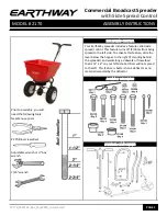
 

PAGE 3 

Step 3: 

Install impeller onto pinion shaft by pressing 

the impeller as shown onto the pinion shaft and turning 
the impeller while holding the pinion shaft to engage 
with the 

COIN

 fully. Press down to secure. 

Next

, insert Cross Brace thru the Gearbox Brace as 

shown. 


Step 4: 

Install gearbox by inserting the pinion shaft into 

hole in center of hoppers bottom.  
 

The word “FRONT” on the GEARBOX must point to 

Front


of the HOPPER. The EarthWay logo is on the front of the 
hopper.


Step 5: 

(A)

 Install lower handles onto the frame to 

both sides as shown. Insert 2¼

 bolt through second hole 

in lower handle and through first hole in frame and install 
locknut. 

DO NOT TIGHTEN

 
(B)

 Now insert 1½

 bolt through first hole in lower 

handle. Then through frame brace. Next into threaded 
connector in cross brace. 

DO NOT TIGHTEN. 

NOTE

: Numbers on frame brace must be facing toward 

gear box as shown. 

(C)

 Next insert 1½

 bolt through other end of frame brace 

and through second hole in frame install locknut.


Step 6: 

Install the axle through the axle hole in the 

lower handle and then through the gearbox and then 
through the lower handle on the other side as shown. 


Summary of Contents for 2170

Page 1: ...CONTROL Your EarthWay spreader includes a feature called side spread control This feature turns off fertilizer from being spread to the left side To activate this feature slide the lever below the ho...

Page 2: ...oroughly after each use Coat all metal surfaces pay special attention to the inside outside of tubing it s easiest to do while assembling with light oil Fluid Film or silicon spray to help prevent cor...

Page 3: ...e EarthWay logo is on the front of the hopper Step 5 A Install lower handles onto the frame to both sides as shown Insert 2 bolt through second hole in lower handle and through first hole in frame and...

Page 4: ...TIGHTEN Step 7 Slide axle bushing over axle and into axle bearing to both sides as shown Step 8 Install drive wheel onto the axle and align with the cotter pin hole nearest to lower handles as shown I...

Page 5: ...4_Rev_May2020_compressed PAGE 5 TURN SPREADER UPRIGHT ON TO WHEELS Step 10 Insert 2 bolt through Gauge Lever assembly next through upper handle then the handle shaft and then the other upper handle an...

Page 6: ...Turn to lock in place Step 12 Insert other end of pivot rod into pivot and bracket assembly as shown Turn to lock in place Step 13 Install handle shaft to lower handles and pivot bracket assembly as s...

Page 7: ...er is in the full open position REMEMBER SETTING 30 ON THE FLOW CONTROL LEVER MUST PLACE THE SHUT OFF PLATE IN THE FULL OPEN POSITION TO BE PROPERLY CALIBRATED Now tighten the nuts against the pivot b...

Page 8: ...the part s or product any labor charges associated with repair or replacement of non conformances are specifically excluded Due to the corrosive nature of most fertilizers and ice melt products Earth...

Page 9: ...d Control slide the control lever from the front to the back This will activate the SideSpred Control for a PARTIAL spread pattern and prevent material from being spread to the left side of the spread...

Page 10: ...3 HANDLE SHAFT SQ 17 42256 CONTROL ROD 18 31138 8 X 3 8 PMT 8 HD COARSE BLACK 19 36300 1 4 20 NYLON INSERT LOCKNUT S S 20 32100 1 4 20 HEX NUT ZINC 21 36208 6 X 3 8 TYPE 25 PHPS S S 22 12317SSC SHUT O...

Page 11: ...the lower nut so that it allows you to push the Control Lever to 30 Next tighten each nut so that they contact the pivot bracket without moving it Carefully tighten each nut fully so they do not loos...

Page 12: ...nd the closest LBS 1 000 square feet in Broadcast Setting Matrix below based on the material particle size Example 2 0 LBS 1 000 square feet Spreader Setting of 10 13 or 18 based on particle size The...

Reviews: