
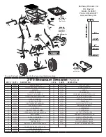


Axle
Bushing
Bearing
Frame brace
1/4-20 Locknut
Lower Handle
Bushing
Shut-Off
1/4-20 x 1-1/2”
Hex Head Bolt
STEP 5B
STEP 5C
1/4-20 x 2-1/4”
Hex Head Bolt
STEP 5A
Foot
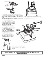
3.
Install impeller onto pinion shaft by pressing the impeller as
shown onto the pinion shaft and turning the impeller while holding
the pinion shaft to engage with the
COIN
fully, and press down to
secure.
Next,
insert Cross Brace thru the Gearbox Brace as shown above.
FRON
T
Impeller
Cross Brace
GEARBOX ASSEMBLY
Gearbox Brace
Pinion
Shaft
Press & turn
Impeller
to engage
Coin securely
Coin
FR
ON
T
4.
Install gearbox by inserting the pinion shaft into hole
in center of hoppers bottom. The word “FRONT” on the
gearbox must point to
Front
of the hopper. The EarthWay
logo is on the front of the hopper.
Axle Bearing
Flat
Side
Notch
NOW GO BACK AND TIGHTEN ALL NUTS AND BOLTS STARTING WITH FIRST STEP.
DO NOT OVER TIGHTEN.
PAGE 2
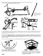
5.
A -
Install lower handles onto the
frame to both sides as shown. Insert 2¼”
bolt through second hole in lower handle
and through first hole in frame and install
locknut.
DO NOT TIGHTEN.
B -
Now insert 1½” bolt through first
hole in lower handle. Then through
frame brace.
NOTE:
Numbers on frame
brace must be facing toward gear box as
shown. Next into threaded connector in
cross brace.
DO NOT TIGHTEN
.
C -
Next insert 1½” bolt through other
end of frame brace and through second
hole in frame install locknut.
6.
Install the axle through the axle hole
in the lower handle and then through
the gearbox and then through the lower
handle on the other side as shown.
NOTE:
Notch on bearings and lower
handles. Bearings must go through flat
side of lower handle (from the outside to
the inside).


