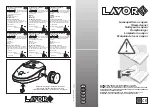
background image

COMPONENTS

The following components are included in the kit (as illustrated below)

WD0001 

Recovery Tank       

WD0036

Crevice Tool

WDACC4 Extension Tubes x 2   

WD0037

Floor Head

WD0029

Paper Filter                     

WD0045

Castors x 4

WD0030 

Foam Filter                     

WD0048

Hose

WD0032 

Rubber Band                    

WD0082 

Motor Housing Assembly

WD0035 

Hose Inlet                      

WD0147 

Outlet Elbow

UNPACKING AND SETTING UP

1) Remove all packing materials and accessories and lift unit out of the box.
2) Release the two tank clips and lift the motor housing off from the recovery tank.
3) Remove all components from inside the tank.
4) Turn the tank upside down and insert the 4 castors. These should be pushed in hard until they stop.

Once installed these remain in place permanently.

5) Push the Hose Inlet into the hole in the side of the Recovery Tank. The Hose Inlet must be pushed in 

from the outside of the Recovery Tank ensuring that the lug on the side of the Hose Inlet is lined up 
with the slot in the hole in the Recovery Tank. Grasp the Hose Inlet from inside the Recovery Tank and 
pull with an up and down motion to engage. Make sure that the clips on the top and bottom of the 
Hose Inlet are fixed into place inside the Recovery Tank. Once installed the Hose Inlet can remain in 
place permanently.

6) Fit the outlet elbow to the outlet on the motor housing. The outlet elbow can be used to deflect airflow 

from the motor away from the work area.

3

WD0046-04-08.qxd  21/7/08  10:54 am  Page 3

Summary of Contents for COMBIVAC

Page 1: ...R PLEASE READ THESE INSTRUCTIONS CAREFULLY BEFORE USE RETAIN FOR FUTURE REFERENCE EARLEX LTD WILL ACCEPT NO RESPONSIBILITY FOR THE USE OF THIS PRODUCT IF USED FOR ANY OTHER PURPOSES THAN THOSE DETAILE...

Page 2: ...erning use of the appliance by a person responsible for their safety l Always switch the unit off before changing between vacuum and blower functions l Earlex recommend the use of appropriate ear prot...

Page 3: ...These should be pushed in hard until they stop Once installed these remain in place permanently 5 Push the Hose Inlet into the hole in the side of the Recovery Tank The Hose Inlet must be pushed in f...

Page 4: ...HED VENTS PAPER FILTER FOAM FILTER WHEN FITTING FOAM FILTER LEAVE AN APPROX 10MM GAP ENSURING ALL ARCHED VENTS ARE COVERED PAPER FILTER PAPER BAG TO EXCEED THE 10MM GAP HOUSING ELASTIC BAND FITTED OVE...

Page 5: ...of dirt have been removed Then rinse through with cold water and allow to dry NOTE It is essential that the foam filter is thoroughly dried before installing paper filter Notes You will need to period...

Page 6: ...f foam Should this occur switch off the unit wash out any foam in the filter and tip away any water around the outlet on the motor housing before restarting EMPTYING TANK WARNING TAKE CARE THE TANK MA...

Page 7: ...use in this lead Motor operates but cleaner fails to pick up Check if the cleaner needs emptying Check and clear any blockages within the system Check that both foam and paper filters are clean and no...

Page 8: ...red brown must be connected to the terminal which is marked with the letter L or coloured red GUARANTEE This product is guaranteed for a period of two 2 years against faulty materials and workmanship...

Reviews: