background image

Page 5

Rectifier

Inverter

Static Switch

Filter

Input

EMI

Output

Charger

Battery

Fig: 1.3

B. External Views

Renata I - Series User Manual

Summary of Contents for Renata - I Series

Page 1: ...Renata I Series User Manual An ISO 9001 2008 Company 5K 7 5K 10K 15K 20KVA UPS ...

Page 2: ...ation 3 Safety Instructions 3 1 Preparation and System Setup 3 2 Installation 3 3 Operating Instructions 4 Maintenance 4 1 UPS Maintenance 4 2 Battery Maintenance 5 Trouble Shooting 6 Technical Specifications 2 3 3 6 6 6 8 10 10 11 11 16 Renata I Series User Manual ...

Page 3: ...ly stable power to Load When AC turns back to the acceptable range of Load Ups automatically adjust power again to the rectifier and inverter Meanwhile UPS charge the Battery During the full courses it has no transfer time from AC to battery backup operating will not be interrupted So we call it true on line UPS Further more when inverter stopped output if UPS fails system will automatically trans...

Page 4: ...l mode As shown in Fig 1 1 the AC power supply passes through rectifier inverter static switch filter to the output and chargers the battery by the charger Rectifier Inverter Static Switch Filter EMI Charger Input Output Battery Fig 1 1 Renata I Series User Manual ...

Page 5: ...e under the following conditions 1 Over Load 2 Inverter Failure 3 The inverter switch on the front panel isn t pushed to the ON or within the initial 25 seconds after it is pushed to ON 4 The inverter switch is pushed to the OFF 2 Power Failure Mode As shown in Fig 1 2 the battery supplies the output to Load through the inverter Renata I Series User Manual ...

Page 6: ...Page 5 Rectifier Inverter Static Switch Filter Input EMI Output Charger Battery Fig 1 3 B External Views Renata I Series User Manual ...

Page 7: ...uble shooting guide when having problems 9 Keep the unit clean all time 3 1 B System setup 1 Precaution 1 Remove all the wires 2 Handle the unit very carefully and avoid dropping 3 Never leave the unit upside down 3 2 Installation Refer to the following Instructions for system install Input a Never plug the unit into a wall outlet The standard 15A wall outlet will not support the heavy load of the...

Page 8: ... the correct Polarity h Avoid sharing the same terminals with other equipments i When wiring is done make sure that no wires touches the metal case to prevent short circuit Renata I Series User Manual 5kVA 192VDC 11 UPS TERMINAL CONNECTION DETAILS 7 5 10 15 20KVA 384VDC 31 UPS TERMINAL CONNECTION DETAILS ...

Page 9: ...te of installation 2 Make sure that the Power switch on the rear panel is OFF 3 Unplug all loads 4 Use a tester to check if the input voltage is at rated level 5 Gently twist the input output wiring and tighten loose ones 6 Inspect the input output fuses to be in working order 3 3 2 Controls and LCD Indicators Renata I Series User Manual 8 7 6 5 10 9 ...

Page 10: ...the Inverter When press SW3 Green the unit will turn ON the inverter and unit transfer from Bypass to Normal operation Power Switch Located at the rear panel of the unit controls the input AC power and Input batteries power for the unit 3 3 3 Power ON Procedure The procedure is very simple Please follow the steps for bellow operations Start Up a Make sure that the power switch is OFF and there is ...

Page 11: ......

Page 12: ......

Page 13: ...ains ON Indication not ON Page 12 A Is power switch ON Turn ON power switch Is Line Indication ON Is the Input Voltage Normal Call for Service Continue Yes No Yes Check the AC Input No No Yes Fig IV 1 Renata I Series User Manual ...

Page 14: ...is ON Turn ON Inverter switch Is Inverter indication ON Did Inverter indicators go off in 20 Sec Disconnect the Loads Continue operation Yes No Yes No Yes No Call for Service Did Inverter indicators go off in 20 Sec Yes Fig IV 2 No Renata I Series User Manual ...

Page 15: ...s ON Turn ON Inverter switch Is Load on Bypass Indication ON after 20 Sec Continue operation Yes No No Yes Yes No Call for Service Is Fault Indicators ON No Fig IV 3 Is the Input Voltage Normal Yes D Disconnect some uncritical loads No Renata I Series User Manual ...

Page 16: ...ion ON D Reconnect all Loads and turn ON No Yes Call for Service Is Fault Indicators ON Yes Fig IV 4 No Turn OFF the Inverter Switch Disconnect Loads Turn ON the Inverter Switch Is Inverter indicators ON B Renata I Series User Manual ...

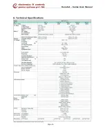
Page 17: ...Page 16 6 Technical Specifications Renata I Series User Manual ...

Page 18: ...oda Bhopal Bhubaneshwar Chandigarh Chennai Cochin Coimbatore Calicut Dehradun Guwahati Gwalior Hubli Hyderabad Indore Jabalpur Jaipur Jammu Kanpur Kolkata Kottayam Ludhiana Lucknow Madurai Meerut Mumbai Munnar Mangalore Mysore Nagpur New Delhi Ongole Palakkad Patna Pondicherry Pune Raipur Ranchi Rajamundry Salem Srinagar Tirupati Trichy Tirunelveli Trivandrum Udaipur Vizag Vijayawada Varanasi Work...

Reviews: