SUBJECT
REF. MDL.
REPORT NO.
INSTRUCTIONS FOR CONTINUED AIRWORTHINESS
GA182
ICA182-2
Rev. A
10/15/12
SEE NON-DISCLOSURE NOTICE ON THE COVER PAGE
24 of 101
Copyright 2012
Eagle Copters
All Rights Reserved
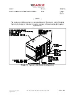
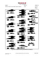
NOTE
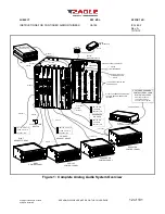
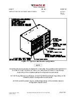
Assembly shown is typical in configuration. Optionally, the quantities and positions for
G11428, G11429, G12358, G11426-4, G11426-8 and G11426-10 may change
depending on the installers desired configuration requirements.
G11437 Relay Module may Replace G11427 COM1 Direct Board depending on the
installers desired configuration requirements.
G11430 Audio Expander may be omitted depending on the installers desired
configuration requirements.
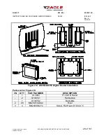
Parts List for Figure 14:
I/N
QTY
PART NUMBER
DESCRIPTION
-
1
G11182
Rail Guide With Camloc Assembly
-
1
G11268
Backplane
-
1
G11426
Shell
-
1
G11426-1
Case
-
1
G11426-3
Side Cover
-
* [a]
G11426-4
Cover Plate
-
* [a]
G11426-8
Wire Guide Cover Panel
-
1 [b]
G11427
COM1 Direct Board
-
1 [b]
G11437
Relay Module Board
-
* [a]
G11428
Audio Board
-
* [a]
G11429
ICS Audio Board
-
* [a][c]
G12358
Headset Expander
-
* [a][c]
G11430
Audio Expander
-
* [a]
G12266
Dimmer Module
-
1
G11700
Backplane Insulator
-
1
G11701
Backplane Insulator (2)
-
* [a]
G12538
GNET Config Port
* [a] Quantities and positions for these components may change depending on the
installer’s desired configuration requirements.
* [b] Audio systems shall be fitted with either one G11427 COM1 Direct OR G11437
Relay Module.
* [c] Audio systems shall be fitted with either G11429 ICS Audio Board OR G12358
Headset Expander Boards.


