50
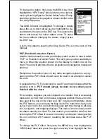
PCF Offset” label. Finally, press the right arrow key
again.
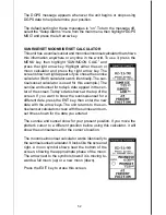
A screen similar to the one at right appears.
Now enter the correction for your location. Remember,
this is the difference between the location shown on
the present position display and the position shown on
the chart. In this example, we entered 0 degrees, 0.047
minutes north latitude and 0 degrees, 0.244 minutes
east longitude. That is the difference between the
present position shown by the Map Guide Pro and the
one on our chart.
After you’ve entered the latitude/longitude correction,
press the ENT key to accept it. The Map Guide Pro
erases the PCF entry screen and returns to the navi-
gation or mapping screens with the correction factor
applied.
POSITION PINNING
When using a GPS receiver at extremely low speeds, it can have trouble
determining your course over ground, or direction you’re travelling. This is
due in large part to SA, or selective availability. SA is small inaccuracies
purposefully put into the GPS satellite’s signal by the government. This
cause wide variations in the track display and other navigation displays
when using the unit at slow speeds.
If you’re using this receiver without DGPS and stop, the position pinning
feature locks the present position indicator on the plotter until you’ve moved
a short distance or exceed a very slow speed. This prevents the “wander-
ing” plot trail seen when you’re stopped with position pinning turned off.
This also affects the navigational displays.
The easiest way to see the effects of S/A is to stand still with the GPS
receiver turned on and watch your plot trail with position pinning turned
off. You’ll see the present position change, speed increase and decrease,
and a random plot trail on the plotter’s screen.
If you wish to turn the position pinning feature off, press the MENU key,
then highlight the “GPS Setup” label and press the right arrow key. Now
highlight the “Pinning” label. Finally, press the left arrow key.


