DB4020 Dual Band 40&20M SSB QRP Transceiver Kit
Page 28
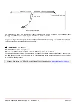
Note: For greater clarity, the drawing shows one black wire and one red wire. In reality, both wires are of
the same color.
R
otary
E
NCODER,
P5
volume potentiometer
P3
Rx
attenuator potentiometer, external
connections
J
acks and
S
witches
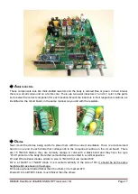
You may prefer to install the jacks, connectors, switches outside the board. Then see the section
"WIRING AND CONNECTIONS"
Now mount and solder the Rotary Encoder, the P2 volume potentiometer (marked B10K) and the P4 Rx
attenuator potentiometer (marked B1K) in their respective positions.
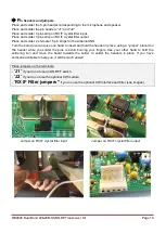
Mount and solder the antenna and
power jacks, phones and speaker jacks, and the SPK-HEAD, EXT-SPK/MIX-SPK switches.
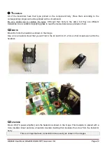
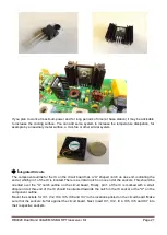
Before mounting the external connection jacks, you should cut the protrusions located at the bottom of
these jacks; otherwise you will not be able to solder them in the correct position. See the image.


