DB4020 Dual Band 40&20M SSB QRP Transceiver Kit
Page 21
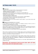
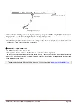
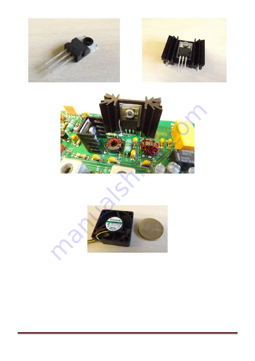
If you plan to work at maximum power and for long periods of time (at base station) it may be advisable
to increase the cooling surface. You can add some system to increase the temperature dissipation, for
example by an auxiliary metal surface, a mini-fan or other similar system.
I
ntegrated Circuits
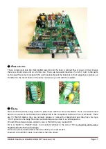
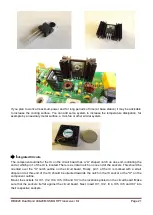
The component outline for the IC on the circuit board has a “U” shaped notch on one end, indicating the
end at which pin 1 of the IC is located. There is a similar notch on one end of the sockets. This should be
oriented over the "U" notch outline on the circuit board. Finally, pin 1 of the IC is marked with a small
dimple or dot; this end of the IC should be oriented towards the notch in the IC socket or the "U" on the
component outline.
Mount the sockets for IC1, IC2, IC4, IC5, IC6 and IC7 in the locations printed on the circuit board. Make
sure that the sockets lie flat against the circuit board. Next, insert IC1, IC2, IC4, IC5, IC6 and IC7 into
their respective sockets.


