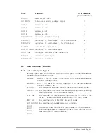
5.2.3
Analogue Outputs
The following analogue outputs are provided to allow the user to implement a simple
and cost effective monitoring system; these outputs are also available in digital form
via the RS-422 or RS-485 serial communications interface (see section 6). These
outputs are referenced to GND (pin P on the user interface connector).
It is recommended that a screened cable is utilised to avoid RFI effects.
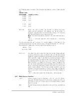
FWD PW MON Provides a 0 to +10 V dc analogue output that corresponds to an RF
output power range of 0 to 200 W. This output is a linear 20 W/V.
Maximum output impedance 100
O
HX I MON
Provides a 0 to +10 V dc analogue output that corresponds to a
TWT Helix current range of 0 to 20 mA. This output is a linear 2 mA/
V. Maximum output impedance 100
O
5.2.4
Control Inputs - Type 1
The following control inputs are of the momentary edge-triggered type. The inputs
are internally pulled up to +15 V by 2k7 resistors. The input is asserted on the falling
edge i.e. as the input is switched to GND (pin P on the user interface connector).
Only one input should be asserted at a time and should be relinquished for at least 10
ms prior to asserting another type 1 input.
Note:
The operation of the XMIT control input is modified while the CTRL O/R input
is asserted. See section 5.2.6.
Minimum pull down time
. . . . . . . . . . . . . . . . . . . . .
1ms
Maximum external switch ‘on resistance’ . . . . . . . . . . . . . .
100
O
OFF
Selects the OFF mode directly from any of the other three operating
modes (WARMUP, STBY or XMIT).
STBY
Selects the STBY mode directly from the XMIT mode. When
selected from the OFF mode the unit is placed into the WARMUP
mode for three minutes before automatically entering the STBY
mode.
XMIT
Selects the XMIT mode directly from the STBY mode. When
selected from the OFF or WARMUP modes, the XMIT mode is
automatically entered after the end of the three minute heater warm
up time.
RED SEL
Part of the redundant switch control facility, selects the amplifier to
be routed to the antenna.
5.2.5
Control Inputs - Type 2
The following control inputs are of the level active type. The inputs are internally
pulled up to +15 V by 2k7 resistors.
Maximum external switch ‘on resistance’ . . . . . . . . . . . . . .
100
O
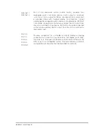
AUTO ENA
Part of the redundant switch control facility, toggles between the
automatic and manual change over mode. In the automatic mode, a
failure of the other amplifier will automatically route this amplifier to
the antenna. GND = Automatic mode, Not Connected = Manual
mode.
RF INHIB
Only operational with the solid state amplifier option. Allows the RF
signal to be inhibited, giving a minimum RF output attenuation of 45
dB. GND = RF Inhibited, Not Connected = RF enabled.
HBN63xx-1, Issue 8, Page 23

