


__________________________________________________________________________________________________________________
European Safety Systems Ltd.
Impress House, Mansell Road, Acton, London W3 7QH [email protected] Tel: +44 (0)208 743 8880
www.e2s.com Fax: +44 (0)208 740 4200
Document No. D211-00-601-IS-SC Issue: F 02-03-2020 Sheet 4 of 9
S2
S3
L
N
E
C
STAGE 4 = S2 + S3
(Customer
Supplied Switches)
STAGE 4 = S2 + S3
(Customer
Supplied Switches)
STAGE 4 = S2 + S3
(Customer
Supplied Switches)
For use in explosive gas atmospheres, a minimum ingress
protection rating of IP54 must be maintained.
NPT stopping plugs should be greased before insertion.
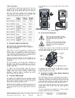
7) Cable
Connections
Electrical connections are to be made into the terminal blocks
on the PCBA located in the enclosure. See section 5 of this
manual for access to the enclosure.
Wires having a cross sectional area between 0.5 mm² to
2.5mm² can be connected to each terminal way. If an
input and output wire is required the 2-off Live/Neutral or
+/- terminals can be used. If fitting 2-off wires to one
terminal way the sum of the 2-off wires must be a
maximum cross sectional area of 2.5mm². Strip wires to
8mm. Wires may also be fitted using ferrules. Terminal
screws need to be tightened down with a tightening
torque of 0.56 Nm / 5 Lb-in. When connecting wires to
the terminals great care should be taken to dress the
wires so that when the cover is inserted into the chamber
the wires do not exert excess pressure on the terminal
blocks. This is particularly important when using cables
with large cross sectional areas such as 2.5mm².
8) AC
Wiring
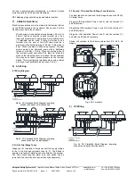
8.1 Wiring Diagram
Fig 3a. AC Simplified Block Diagram, powering
sounder and beacon simultaneously
L
N
C
S2
N
L L L N
N
S3
C
L L
N
N
S2
S3
C
S2
N
L L L N
N
S3
L L
N
N
L
N
Fig 3b. AC Simplified Block Diagram, powering
sounder and beacon independent
8.2 Unit’s First Stage Tones
Stage one (S1) operation: Simply connect the supply voltage
to the L and N supply terminals, (see fig. 3). The Strobe is
powered via factory installed wires connected to the sounder.
The wires connecting the alarm horn and strobe can be
removed if the user wishes to power the strobe separately.
8.3 Second, Third and Fourth Stage Tone Selection
To select the second, third and fourth stage tones on the D2xS1
AC alarm horns.
Stage two (S2) operation: Power L and N, link the common (C)
and S2 terminal.
Stage three (S3) operation: Power L and N, link the common (C)
and S3 terminals.
Stage four (S4) operation: Power L and N, link the common (C)
and both the S2 and S3 terminals.
Strobe will continue to flash during alarm horn S2, S3 & S4
stages.
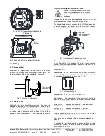
9) DC Wiring
Fig. 5a DC Simplified Block Diagram, powering
sounder and beacon simultaneously
LL NN EE
L
N
C
S2
N
L L L N
N
S3
C
L L
N
N
S2
S3
C
S2
N
L L L N
N
S3
L L
N
N
+
-
S2
-
+ + + -
-
S3
S2
S3
-
-
+ +
S2
-
+ + + -
-
S3
-
-
+ +
Fig. 4 AC Terminals


