


__________________________________________________________________________________________________________________
European Safety Systems Ltd.
Impress House, Mansell Road, Acton, London W3 7QH [email protected] Tel: +44 (0)208 743 8880
www.e2s.com Fax: +44 (0)208 740 4200
Document No. D211-00-601-IS-SC Issue: F 02-03-2020 Sheet 3 of 9
147,0mm [5,73in.]
116,0mm [4,52in.]
21
3,
3mm
[
8
,3
2i
n.
]
165,6mm [6,46in.]
9,7mm [0,38in.]
6,
7mm
[
0
,2
6i
n.
]
Ø6,9mm [Ø0,27in.]
310
,3
mm [
12,
10
in
.]
125,0mm [4,88in.]
179,2mm [6,99in.]
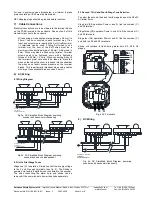
Beacon
Cover
M4 Screws
(4-off)
Sounder
Cover
M4
Screws
(4-off)
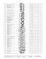
2.8 Electrical Ratings
It is important that a suitable power supply is used to run the
equipment. The power supply selected must have the
necessary capacity to provide the input current to all the units.
The input current will vary according to the voltage input level.
The current levels shown above are for the worst-case input
voltage and flash setting resulting in max. current.
Part No.
Nominal
Voltage
Beacon
Current
Sounder
Current
D2xC2X05DC024 20-28Vdc
296mA
313mA
D2xC2X05DC048
48Vdc
145mA
181mA
D2xC2X05AC115
115-120Vac
50/60Hz
80mA
89mA
D2xC2X05AC230
220-230Vac
50/60Hz
30mA
52mA
D2xC2X10DC024 20-28Vdc
609mA
313mA
D2xC2X10DC048
48Vdc
260mA
181mA
D2xC2X10AC115
115-120Vac
50/60Hz
185mA
89mA
D2xC2X10AC230
220-230Vac
50/60Hz
107mA
52mA
3) Special Conditions for Safe Use
Special Condition for safe Use as stated on the Type
Examination Certificate DEMKO 14 ATEX 4786493904X /
CoC IECEx ULD 14.0004X:
When used for a Group III application, the surface of the
enclosure may store electrostatic charge and become a
source of ignition in applications with a low relative humidity
<~30% relative humidity where the surface is relatively free of
surface contamination such as dirt, dust, or oil.
Guidance on protection against the risk of ignition due to
electrostatic discharge can be found in EN TR50404 and IEC
TR60079-32.
End user shall adhere to the manufacturer’s installation and
instruction when performing housekeeping to avoid the
potential for hazardous electrostatic charges during cleaning,
by using a damp cloth.
To maintain the ingress protection rating and mode of
protection, the cable entries must be fitted with suitably rated,
certified cable entry and/or blanking devices during
installation. If conduit is used for installation, seal conduit
within 18 inches from the enclosure.
4) Location and Mounting
The location of the combined alarm horn and beacon should
be made with due regard to the area over which the warning
signal must be visible and audible. It should only be fixed to
services that can carry the weight of the unit.
DxC2 Alarm Horn and Strobe to a flat surface via the two 9.7
x 6.7mm, 147mm pitch fixing holes in the mounting feet of the
sounder section and the two 7mm fixing holes in the feet of
the base.
The equipment is not to be mounted with the horn facing
upwards.
Fig. 1 Fixing locations.
5) Access to the Enclosure
To access the enclosures, loosen the four M4 posi pan head
screws for beacon and/or the four M4 posi pan head screws for
the sounder and withdraw the cover/s.
Fig. 2 Accessing Enclosures.
To replace cover, check that the ‘O’ ring seal is in place.
Carefully push the cover in place. Insert M4 screws with fiber
washers and tighten to 3Nm torque.
6) Selection of Cable, Cable Glands, Blanking
Elements & Adapters
When selecting the cable size, consideration must be given to
the input current that each unit draws (see Table 1), the number
of beacons on the line and the length of the cable runs. The
cable size selected must have the necessary capacity to provide
the input current to all of the sounders connected to the line.
If a high IP (Ingress Protection) rating is required then a suitable
sealing washer must be fitted under the cable glands or
blanking plugs.
For use in explosive dust atmospheres, a minimum ingress
protection rating of IP6X must be maintained.
Warning – High voltage may be present,
risk of electric shock. DO NOT open when
energised, disconnect power before
opening.
Warning –
Hot surfaces. External surfaces
and internal components may be hot after
operation, take care when handling the
equipment.


