background image


E2S


Telephone:


+44


(0)20


8743


8880


Fax:


+44


(0)20


8740


4200


Email:


[email protected]


www.e2s.com


DC

067_Issue_H


(D1x).docx

 ‐ 

Page


2


of


2

 ‐ 

QAF_252_Issue_5


Martin


Streetz


Document


No.:


DC

067_Issue_H


Quality


Assurance


Manager


Date


and


Place


of


Issue:


London,


10/02/2022


EU


Declaration


of


Conformity


On


behalf


of


European


Safety


Systems


Ltd.,


I


declare


that,


on


the


date


the


equipment


accompanied


by


this


declaration


is


placed


on


the


market,


the


equipment


conforms


with


all


technical


and


regulatory


requirements


of


the


above


listed


directives,


regulations


and


standards.


This


Declaration


is


issued


under


the


sole


responsibility


of


the


manufacturer.


Summary of Contents for D1xS2HDC024-S

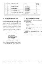
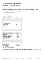
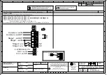
Page 1: ...WARNING FIT SEALING FITTING IN CONDUIT RUNS WITHIN 18 INCHES FROM ENCLOSURE EQUIPMENT MUST NOT BE INSTALLED WITH THE HORN FACING UPWARDS OF HORIZONTAL DO NOT OPEN WHEN AN EXPLOSIVE ATMOSPHERE IS PRESENT DO NOT OPEN WHEN ENERGISED POTENTIAL ELECTROSTATIC CHARGING HAZARD CLEAN ONLY WITH A DAMP CLOTH ENCLOSURE ENTRIES TWIN M20 X 1 5 SINGLE 1 2 NPT ATEX IECEx UKEx INSTALLATIONS IF TEMPERATURE EXCEEDS ...

Page 2: ... IIC T6 Gb Ta 55 C to 60 C Ex tb IIIC T95 C Db Ta 55 C to 75 C See Product table for electrical ratings of each unit model Certificate No DEMKO 19ATEX2141X IECEx ULD 19 0008X UKEx UL UL21UKEX2132X Epsilon x Equipment Group and Category II 2G II 2D CE Marking and Notified Body No 2813 UKCA Marking and Notified Body No 0518 4 Zones Gas Group Category and Temperature Classification The units can be i...

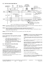
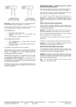
Page 3: ...ld up of electrostatic charges on non conducting surfaces Only the explosionproof cover is to be used for access to the enclosure for installation service and maintenance 6 Specific Conditions for Safe Use Flameproof threaded joints and cemented joints are not permitted to be repaired 7 Product Mounting and Access 7 1 Mounting The D1x Alarm Horn may be secured to any flat surface using at least tw...

Page 4: ... on the line and the length of the cable runs The cable size selected must have the necessary capacity to provide the input current to all the sounders connected to the line DC 0 2 2 5mm2 AWG24 AWG12 Fig 3 Wire Preparation When connecting wires to the terminals great care should be taken to dress the wires so that when the cover is inserted into the chamber the wires do not exert excess pressure o...

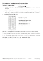
Page 5: ...switching Fig 6 Stage Switching Polarity 9 3 Tone Selection The D1x Alarm Horn Sounders have 64 different tones that can be selected independently for the first and second stage alarms The tones are selected by operation of the tone setting DIP switch 1 DIP switch 2 see fig 7 on the PCB for stage 1 and stage 2 respectively Default Switch 2 S2 Tone 1 0 0 0 0 0 0 Default Switch 1 S1 Tone 44 1 1 0 1 ...

Page 6: ... 0 5W or a minimum resistance value of 500 ohms and a minimum wattage of 2W The resistor must be connected directly across the ve and ve terminals as shown in the following drawing The resistor leads should be kept as short as possible SIL2 line monitoring module product version see section 20 for standard default values and product coding See document D190 06 651 for associated wiring diagram Fig...

Page 7: ... End of Line Devices may be fitted between the ve ve terminals of the PCBA Please ensure that the device legs meet the wire size range stated for the connection terminals and are fitted correctly in order to avoid a short Refer to the compatible control panel specification for EOL device values and ratings Model Nominal Voltage Voltage Range P1 Nominal Operating Current P2 Nominal Operating Curren...

Page 8: ...operates as part of a SIL 2 system The sounder will after commissioning remain powered in Standby mode reverse polarity until the sounder is required to operate When the signaling device is required to operate the polarity is changed to normal supply and the sounder will go into Active mode where it will start to sound the correct tone When periodically testing the system and sounders operation is...

Page 9: ...arity mode When Commissioning system the power must not be disrupted to the SIL 2 Unit within the unit s initialization cycle which is 5 seconds Once past this period the SIL 2 system is fully operational and will be in monitoring the sounder and power in Standby mode The relay RLY1 2 on the SIL 2 unit will only remain open for a maximum of 1 second on commissioning start up RLY1 2 will subsequent...

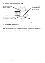
Page 10: ...ounder check on pattern generation and signal output checks Important Only tones use tones that are stated as SIL 2 approved for the SIL 2 application Ensure that the unit is set to one of these tones see in Tone Table D221 95 651 IS As factory default the sounder should be set to Stage 1 Dip SW1 to Tone 44 and Stage 2 Dip SW2 to Tone 1 J3 Header Hard Reset Shown in factory default position A see ...

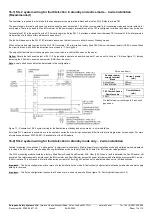
Page 11: ...rom the circuit Note a cable short circuit will not be detectable in this configuration For one unit only Sounder power supply terminal block Current drawn mA Active Mode 190mA Standby Mode 25mA SIL2 TB1 Current Sense Resistor value Current drawn mA 3 3kΩ 7 2mA On fault mode current drops to 0 as circuit goes open Figure 11 Schematic of SIL 2 system wiring for fault detection in standby and active...

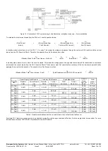
Page 12: ... SIL 2 alarm horn sounders are to be cabled in series the monitoring connections differ from that of a single alarm horn sounder For more information see manual D197 00 651 IS available from the E2S website I Total Current drawn IFR Current drawn from Fault Resistor IEOL Current drawn from Customer EOL resistor ISIL Current drawn from SIL board INF Standby Mode Total Current drawn No Fault IFR 0mA...

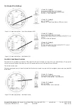
Page 13: ...tion B pins 2 3 linked Places power supply terminal Fault resistor RLY 1 2 in circuit As used in 2 Wire Configuration Figure 14 J2 Header pin positions Fault Resistor FR 16 4 SIL 2 Hard Reset Function Power down the unit completely for a minimum of 30 seconds Move the hard reset header pin Jumper J3 to reset position B shown Then power the unit for a minimum of 5 seconds Power down the unit for 30...

Page 14: ...no input D1xS2FDC024 S D1xS2HDC024 S Failure to Sound Integrity in respect of failure to release SIL 2 Total Failure rate 0 447 pmh hazardous failure rate revealed 0 443 pmh hazardous failure rate unrevealed 0 004 pmh safe failure rate revealed 0 002 pmh safe failure rate unrevealed 0 Diagnostic Coverage 99 System type B Hardware Fault Tolerance 0 Safe Failure Fraction 99 PFD hazardous failure 3 3...

Page 15: ...values of resistors available are shown in table 7 below Code Resistor Value Default resistor coding as follows D1xS2FDC024AB1S1R AFZ Example of a custom requirement resistor coding D1xS2FDC024AB1S1R GEF Where the FR Fault Resistor is G 3 9 kΩ CSR Current Sense Resistor is E 2 7 kΩ EOL End Of Line resistor is F 3 3 kΩ A 2 2 kΩ B 1 0 kΩ C 1 5 kΩ D 1 8 kΩ E 2 7 kΩ F 3 3 kΩ G 3 9 kΩ H 4 7 kΩ J 5 6 kΩ...

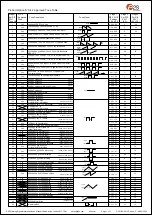
Page 16: ... 0 1 0 0 1 0 1 1 0 0 1 0 0 0 1 0 1 0 1 0 1 0 1 0 0 1 1 0 1 0 1 1 1 0 1 0 1 1 0 1 1 0 0 0 1 1 1 0 0 1 1 1 1 0 0 0 0 0 0 1 0 1 0 0 0 1 1 1 0 0 0 1 0 0 1 0 0 1 1 0 1 0 0 1 0 1 1 0 0 1 1 1 1 0 0 1 0 0 0 1 0 1 0 1 0 1 0 1 1 0 1 1 0 1 0 1 1 1 0 1 1 1 1 1 0 1 0 0 0 0 1 1 1 0 0 0 1 1 0 1 0 0 1 1 1 1 0 0 1 1 0 0 1 0 1 1 1 0 1 0 1 1 0 1 1 0 1 1 1 1 1 0 1 1 0 0 0 1 1 1 1 0 0 1 1 1 0 1 0 1 1 1 1 1 0 1 1 1 0 0...

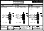
Page 17: ...ve OUT Common ve IN Common ve OUT Stage 2 ve Stage 1 ve IN Stage 1 ve OUT Common ve IN Common ve OUT Stage 2 ve Stage 3 ve EOL EOL S2 EOL S2 S3 Stage 1 ve IN Stage 1 ve OUT Stage 1 ve IN Stage 1 ve OUT Single Stage Configuration Config 1a Line Monitoring Set to positive switching default Stage 1 Apply Power to Stage 1 ve Stage 1 ve For full 4 Wire SIL 2 Connection Monitor SIL 2 ve and SIL 2 ve Ter...

Page 18: ...S NTS SWITCHES FOR STAGE OPERATION CUSTOMER SUPPLIED Stage 2 ve Common ve IN Common ve OUT Stage 1 ve OUT Stage 3 ve Stage 1 ve IN H2 H1 OF 2 2 EOL S2 S3 OPTIONAL LINE MONITORING RESISTOR CUSTOMER SUPPLIED EOL Set H1 H2 to ve switching Three Four Stages Voltage Free 2nd 3rd 4th Stage Activation Configuration Config 2 Common Positive Customer Set H1 H2 to Negative Switching See Below Stage 1 Apply ...

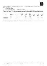
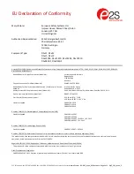
Page 19: ...awarden Industrial Park Hawarden Deeside CH5 3US UK Quality Assurance Notification Module D SIRA 05 ATEX M342 Provisions fulfilled by the equipment II 2G Ex db IIC T6 T3 GB II 2D Ex tb IIIC T82 C 145 C Db Standards applied EN 60079 0 2018 EN 60079 1 2014 EN60079 31 2014 Directive 2014 30 EU Electromagnetic Compatibility Directive EMC Standards applied EN 61000 6 1 2007 EN 61000 6 2 2005 EN 61000 6...

Page 20: ...te and Place of Issue London 10 02 2022 EU Declaration of Conformity On behalf of European Safety Systems Ltd I declare that on the date the equipment accompanied by this declaration is placed on the market the equipment conforms with all technical and regulatory requirements of the above listed directives regulations and standards This Declaration is issued under the sole responsibility of the ma...

Page 21: ... CH4 9JN UK Quality Assurance Notification Module D CSAE 22UKQAN0046 Provisions fulfilled by the equipment II 2G Ex db IIC T6 T3 GB II 2D Ex tb IIIC T82 C 145 C Db Standards applied EN 60079 0 2018 EN 60079 1 2014 EN60079 31 2014 Directive 2014 30 EU Electromagnetic Compatibility Directive EMC Standards applied EN 61000 6 1 2007 EN 61000 6 2 2005 EN 61000 6 3 2007 A1 2011 AC 2012 EN 61000 6 4 2007...

Page 22: ...ate and Place of Issue London 24 02 2022 UKCA Declaration of Conformity On behalf of European Safety Systems Ltd I declare that on the date the equipment accompanied by this declaration is placed on the market the equipment conforms with all technical and regulatory requirements of the above listed directives regulations and standards This Declaration is issued under the sole responsibility of the...

Reviews: