16
OPERATION
1
Channel Selector
: Click on button and select the channel you want to
use from the drop down menu. Scroll up and down the menu with the
arrow keys to see the 10 programmable channels. Channel frequencies and
mission names are edited in the Tracker/Preferences menu (see 12).
2
Channel Number
: Indicates current channel selected.
3
Mission Name
: Defaults to channel frequency. Can be user-defined in
Tracker/Preferences menu (see page 19).
4
Filter/Raw
: Toggles ON/OFF Instantaneous (Raw) Bearing feature.
Button name indicates mode to switch to.
5
Bearing History
: Indicates sampling of RDF signal received in the past
15 seconds.
6
Averaged Bearing
: Shows calculated average of RDF signal history
received. When GPS Tracking is OFF, bar is red. When GPS Tracking is ON
bar is yellow as long as GPS data is good.
7
Instantaneous Bearing
: In RDF Tracking mode with Filter set to RAW
data, blue arrow indicates bearing of each received signal. In GPS Tracking
mode arrowhead turns red indicating absolute direction to received GPS
coordinates. Arrowhead turns yellow (stale) if two GPS updates in a row are
missed.
8
Beacon Pulse Indicator
: Tail Lights flash to indicate each pulse received
from Beacon.
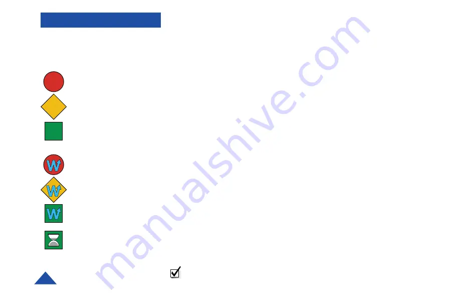
9
Communication Link Status Indicator
: Icon represents status of
communication between Control Head and E-TRAK/R receiver for either
cabled or wireless link.
Cabled Mode
RED Circle =
No communications
YELLOW Diamond =
Connection initiated
GREEN Square = Ready
Wireless Mode
RED Circle with “W”=
Wireless communication
missing.
YELLOW Diamond =
Connection instigated
GREEN Square with “W” =
Communicating in
Wireless Mode
GREEN Square with
Hour Glass = Transferring
mission parameters
Communication Link
Status Indicators
NOTE:
For information on wireless “paired” settings between the
E-TRAK/R and PDA Control Head see page 25.
Summary of Contents for 5000
Page 1: ...RDF Pulse and GPS Enhanced Tracking System...
Page 29: ...35 NOTES...