background image

23

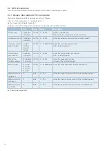
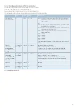
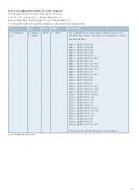
9.2.3  Configuration data for one channel

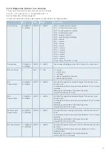
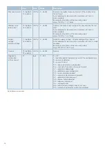
The configuration data for one channel consist of 2 bytes.
Class ID = 101, Instance ID = 1…32 and Attribute ID = 6
Service Code: Get_Attribute_Single (14), Set_Attribute_Single (16)
All configuration data with possible conditions are described in the following table.

Byte

Type

Range

Description

Circuit breaker 
p/n

0 HighByte
1 LowByte

UInt16 0 ... 65535

The expected device type is adjusted here for the channel. 
The device type always influences a circuit protector, i.e. both 
possible channels.

36873 = REX12D-TA1-100
36874 = REX12D-TA2-100
36873 = REX12D-TA1-100
36874 = REX12D-TA2-100
36878 = REX12D-TE2-100
36910 = REX12D-TE2-100-CL2
36905 = REX12D-TB1-100
36937 = REX12D-TA1-100-CL2
36969 = REX12D-TB1-100-CL2
36906 = REX12D-TA2-100-CL2
36942 = REX12D-TE2-101
36974 = REX12D-TE2-101-CL2
37001 = REX12D-TA1-101
36938 = REX12D-TA2-101
37033 = REX12D-TB1-101
37065 = REX12D-TA1-101-CL2
37097 = REX12D-TB1-101-CL2
36970 = REX12D-TA2-101-CL2
37130 = REX22D-TD2-100-CL2
37162 = REX22D-TD2-100
37129 = REX22D-TD1-100
37161 = REX22D-TA1-100
37134 = REX22D-TE2-100
37166 = REX22D-TE2-100-CL2
37194 = REX22D-TD2-101-CL2
37226 = REX22D-TD2-101
37193 = REX22D-TD1-101
37225 = REX22D-TA1-101
37198 = REX22D-TE2-101
37230 = REX22D-TE2-101-CL2

This list may be extended by future circuit protectors.

fig. 23: Configuration data channel

Summary of Contents for EtherNetIP ControlPlex CPC12EN

Page 1: ...User Manual ControlPlex Controller CPC12EN...

Page 2: ...4 LED status indication 8 4 Mounting and installation 9 4 1 Mounting of the system 9 5 Operating modes of the CPC12 bus controller 10 5 1 Operating mode Start up mode 10 5 2 Operating mode System err...

Page 3: ...Non cyclical data 17 9 1 CPC12 controller 18 9 1 1 Device information CPC12 controller 18 9 1 2 Configuration data CPC12 controller 19 9 1 3 Action commands CPC12 controller 20 9 1 4 Dynamic informati...

Page 4: ...Qualified personnel This user manual must exclusively be used by qualified personnel who are able based on their training and experience to realise arising problems when handling the product and to av...

Page 5: ...It consists of electronic circuit protectors which are connected with each other via an integrated connector arm without requiring additional components Power supply is via the EM12 supply module whi...

Page 6: ...on of all measuring values and status information independently of the control system e g to a superordinate cloud application Revised measuring values of all electronic circuit protectors are also fo...

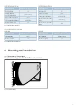
Page 7: ...8 5 92 snap on socket for rail EN 60715 35x7 5 not included Ensure space for plugs and cables Label e g from Phoenix Contact ZBF 21 connector arm X1 Ethernet interface XF1 EtherNet IP interface XF2 Et...

Page 8: ...switch connection sleeve XF1 XF2 XF1 Connection to bus system EtherNet IP Type RJ45 When wiring and connecting to the bus system EtherNet IP the installation and wiring regulations of the EtherNet IP...

Page 9: ...king Double IP detected red Operating mode Indication of operating mode Switched off off Operation mode green Device not configured green blinking Severe but recoverable error red blinking Severe not...

Page 10: ...f the various electronic circuit protectors After a fieldbus connection is established this operating mode will be left and the control unit will take over control again as master If during this time...

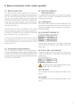
Page 11: ...ters for address slot Transmission of the parameters will be without interruption of the cyclical data exchange between the CPC and the electronic circuit protector 6 3 About the additional Ethernet i...

Page 12: ...F6 The EtherNet IP interface requires several mandatory objects These are the identity object 0x01 the connection manager object 0x06 the device level ring object DLR 0x47 the TCP IP interface object...

Page 13: ...endor Revision 4 USINT USINT Revision of the item Status 5 WORD Summary status of device Serial Number 6 UDINT Serial number of device Product Name 7 SHORT_ STRING Profile ID State 8 USINT 2 Standby 3...

Page 14: ...troller Originator Target bytes 0 1 The 2 input bytes contain the following global error and diagnostic messages 8 2 I O data input total current Originator Target bytes 2 3 The total current supplies...

Page 15: ...UInt16 0 65535 A standardised 16 bit value with a resolution of 10 mA is made available Example for calculation of the measuring value value 150 100 1 50 Amps Load voltage channel 1 3 HighByte 4 LowBy...

Page 16: ...the REX sequence Status controller address 0 1 total current address 2 3 circuit protector 1 channel 1 1 status address 4 load current address 5 6 load voltage address 7 8 circuit protector 1 channel...

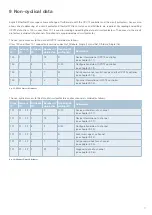
Page 17: ...d as follows Class ID Instance ID Attribute ID Number of data bytes Reading R writing W Description 100 1 1 19 R Device information of CPC12 controller see chapter 9 1 1 100 1 3 5 R W Configuration da...

Page 18: ...n of the installed product Internal assembly order numbers 4 HwHb 5 HwLB 6 LwHB 7 LwLB UInt32 0 4294967295 Holds the assembly order number of the installed product Internal order split number 8 HighBy...

Page 19: ...65535 Each bit represents a channel bit 0 channel 1 bit1 channel 2 If the bit is set this means that the channel cannot be switched on or off via the control unit or the web server Control commands di...

Page 20: ...s interruption True status is maintained writing via web server permitted True 2 The command 131 back to box within the action commands for the CPC12 shall reset the following data Parameters rated cu...

Page 21: ...Service Code Get_Attribute_Single 14 Set_Attribute_Single 16 All device parameters with possible conditions are described in the following table Byte Type Range Description Cycle time ELBus 1 0 HighB...

Page 22: ...the hardware version of the installed product Internal assembly order 4 HwHb 5 HwLB 6 LwHB 7 LwLB UInt32 0 4294967295 Holds the assembly order number of the installed product Internal order split numb...

Page 23: ...874 REX12D TA2 100 36873 REX12D TA1 100 36874 REX12D TA2 100 36878 REX12D TE2 100 36910 REX12D TE2 100 CL2 36905 REX12D TB1 100 36937 REX12D TA1 100 CL2 36969 REX12D TB1 100 CL2 36906 REX12D TA2 100 C...

Page 24: ...C lock bit of each channel default True i e channel not controllable by PLC configured device types default REX12D TA1 0x9009 36873 the statistical values min 655 35 A V max 0 A V avg 0 A V of the cha...

Page 25: ...device failure Min Load voltage 5 HighByte 6 LowByte UInt16 0 65535 Contains the highest measured voltage of the channel since the last reset A standardised 16 bit value with a resolution of 10 mV is...

Page 26: ...0 65535 Holds the supply voltage actuator voltage of the channel A standardised 16 bit value with a resolution of 10 mV is made available Example for calculation of the measuring value value 2512 100...

Page 27: ...es 13 fig 11 Cyclical diagnostic data CPC12 14 fig 12 Total current 14 fig 13 Input data circuit protector 15 fig 14 Output data circuit protector 16 fig 15 CPC12 Object Attributes 17 fig 16 Channel O...

Page 28: ...Altdorf GERMANY Phone 49 9187 10 0 Fax 49 9187 10 397 E mail info e t a de www e t a de Bedienungsanleitung Instruction manual CPC12EN Tx xxx ENG Bestell Nr Ref number Y31363902 Index Issue 01 2021 A...

Reviews: