


8
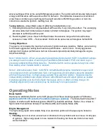
FIX/MIN (blue)
Background
LED color is
GREEN
.
MAX (white)
Orientation will flip for
installations rotating in
opposite direction
(DIR).
Fig A
TC (yellow/tone)
Tone Positions:
Tone with yellow
LED at TC.
Tone (no LED) at 20
and 25-degrees,
serving as a general
position reference.
LED and Tone Signals
1)
RED LED
indicates CAUTION
. When ignition
is powered ON and kill switch (p-lead) is ON the
unit is capable of firing plugs (“HOT”).
a) Steady RED indicates Variable Mode HOT.
b) Blinking RED indicates Fixed Mode HOT.
2) Other LED colors are enabled by turning kill
switch to OFF (ground p-lead). Plug firing is
blocked when displaying other colors.
a) Background color is GREEN.
b) Setpoints:
i)
YELLOW*
(with tone) signals ignition TC
setpoint.
ii)
BLUE
signals MIN setpoint, the lower end
of the firing range in Variable Mode or the fixed firing position in Fixed Mode.
iii)
WHITE
signals MAX setpoint, the upper end of the Variable Mode firing range.
3) Tones will sound at:
a) The stored ignition TC position (with YELLOW LED).
b) Ignition 20 and 25-degree positions. Tones are for the sole purpose of helping installers
locate their chosen MIN and MAX setpoints. After setting TC, these tones will flag the 20
and 25-degree positions
– see Fig A. Other positions (18, 22, 35, etc.), if needed, can be
interpolated from these fixed reference locations.
* YELLOW is a composite color where two LED elements produce a dull and slight shimmering
yellow effect (a limitation of this style LED).
Engine Attachment
First, verify the studs and clamps on hand are compatible
with the E-MAG flange. E-
MAG flange is 0.19” thick - not
compatible with 0.31” clamps common with certain
magnetos. Remove magneto spacers (highlighted area in
photo) and long studs. Long studs are identified by the
roughly 1.75” of exposed stud. Replace with short studs
(#31C12) that will have roughly .75” of exposed stud when
installed. Ignitions will be secured by:
1) Two studs - one above and one below each ignition
station.
2) Mounting clamps will fit over each stud and secure the ignition flange (with fiber gasket) to the
case - see Setup below.


