background image


39


Net DVR

  4.3.3 Data Management

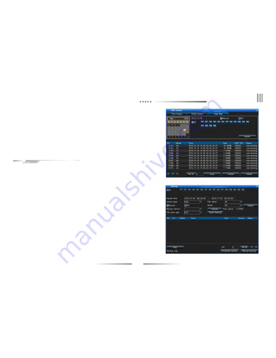
      You can lock, unlock or delete the files in “Data Management”, the interface as the right picture:

l

   Choose the data type: record or picture.

l

   Choose the channel for inquiry.

l

   Use mouse to select data for lock, unlock and delete.

Note: Only when data in unlock status can do lock or delete operation. the recording file which is in

recording process can’t be deleted, when data is in lock status only can be unlocked, can’t be deleted.

       There are 3 ways for the system to backup:

1. Backup to remote PC via network (refer to client instruction).

2. USB disk backup, supporting hot plug, the format of backup disk must be FAT32.

3. Support external USB burner backup record.

“Main Menu” -> “Backup Management” to enter the interface as the right picture:

l

   Backup channel: Choose the channel for backup.

l

   Inquiry time: Input the time period for backup, support maximum 1 month for inquiry.

l

   Device type: Choose the different device type to query the local HDD saving data or

       backup data of every devices.

l

   File status: Lock or unlock.

l

   Data type: Record or picture.

l

   Type: Choose the record type for backup.

l

   Backup device: Choose the backup saving device.

l

   File saved type: Support record saved as DAT, AVI, pictures saved as DAT, JPEG.

Note: 1, Before backup or query the data of backup device, you must choose file saved type.

         4.4  Backup Management

2, The backup data playback in DVR don’

t support other type of files except DAT.

eLineTechnology.com

Summary of Contents for ELI-PRO3 series

Page 1: ...tween product function and operation It is for reference only We will not provide any new information separately for later firmware update The updating files will be added into the new edition of the user manual and will also be posted on our website in the download center This user manual may have some inaccuracy or misprint We sincerely hope your timely feedback and comments to let us correct an...

Page 2: ...Main Functions 8 Chapter3 Equipment Installation and Illustration 12 3 1 Installation Environment and Cautions 12 3 1 1 Attentions on Installing Hard Disk 13 3 2 Package Checking 13 3 3 Device Interface 14 3 3 1 Video Audio Connection 14 3 3 2 USB Backup Interface 14 3 3 3 Network Interface 14 3 3 4 Alarm Input Output Connection 14 3 3 5 RS 485 Connection 18 eLineTechnology com ...

Page 3: ...1 Menu Structure Chart 26 3 7 2 Menu Option Schedule 27 Chapter4 Device Operation 33 4 1 Power On 0ff and Login Lock 33 4 1 1 Keystroke Unlock Lock 33 4 1 2 System Login 33 4 1 3 System Lock 34 4 1 4 Main Menu 34 4 1 5 Status Bar 34 4 2 Power on Wizzard 35 4 3 Data Inquiry and Playback 36 4 3 1 Time Inquiry 36 4 3 2 Event Inquiry 36 4 3 3 Data Management 39 4 4 Backup Management 39 eLineTechnology...

Page 4: ...ord 43 4 5 5 Manual Snapshot 43 4 5 6 Schedule Record 44 4 6 Alarm Setup 44 4 6 1 Motion 44 4 6 2 Sensor 46 4 6 3 Alarm Output 46 4 6 4 Other Alarms 47 4 6 5 Manual Alarm 47 4 7 System Setup 48 4 7 1 General Setting 48 4 7 2 Time Setting 49 4 7 3 Output Setting 50 4 7 4 COM Setting 53 4 7 5 PTZ Setting 54 4 7 6 Network Setting 56 4 7 7 Input Settings 61 4 8 HDD Management 61 eLineTechnology com ...

Page 5: ...6 4 9 6 Input State 66 4 10 System Maintenance 67 4 10 1 Quick Settings 67 4 10 2 User Management 67 4 10 3 Reset to Default 68 4 10 4 Upgrade Management 69 4 10 5 Timing to Restart 71 4 11 Logout Shutdown Reboot 72 4 12 Password Reset 72 4 13 Power Resume 72 Appendix 1 IE Operation Instructions 73 1 LAN Configuration for IE Browse 73 2 WAN Operation Instructions 74 Appendix 2 Net DVR Q A 77 eLine...

Page 6: ...nd reliability This series of equipment use private file systems MFS V2 0 namely flow media file system second edition This file system is based on Microsoft FAT32 to innovate suitable for DVR special file system support more than 2TB hard disk Long time operation does not produce disk fragments Reasonable flow media operation scheduling the operation has fast response Increase check protection in...

Page 7: ...larm output Normal on relay output 3 Video compression Compression arithmetic H 264 Default resolution FD1 PAL 704 576 25 fps ch NTSC 704 480 30 fps ch Resolution 960H PAL 928 576 25 fps ch NTSC 928 480 30 fps ch 4 Audio compression Compression arithmetic G 711A Audio sampling rate 8K sample sec 16 bit sample 5 Code stream type VBR CBR 6 Operation System Linux 7 HDD interface support 48bit LBA wor...

Page 8: ...o stream are synchronous when playback or setting disable audio with the sampling rate of 8K sample sec 16 bit sample 5 Supporting dual stream compression main code stream used for local storing sub code stream used for image transmission in low bandwidth network 6 6 levels of record quality is available to select Users can choose according to requirements so that the recording time is long enough...

Page 9: ...ormation graphical display and play 4 Support zoom in on playback 5 Support full realtime quick playback 6 Support inquiry other time channel recording files through list to playback u Real time survillance features 1 Support HDMI VGA CVBS dual output with different source 2 Support SPOT sequence output 3 Support 1 4 8 9 13 16 ch preview the order of channels can be adjusted and the time position ...

Page 10: ...u Alarm inspection functions 1 Local alarm manual alarm video lost alarm motion detection alarm sensor alarm HDD faulty alarm temperature alarm network disconnect alarm video shield alarm 2 Video lost alarm motion detection alarm sensor detection alarm response on time 3 Network alarm linkage upload alarm signal sound alarm through the PC own horn 4 Video motion detection function each channel can...

Page 11: ...y 2 Perfect log search function 3 System lock keystroke lock password verification multi level user authorization using the username and password as encryption key of code stream when transmission 4 Video lost alarm motion detection alarm and sensor alarm can be informed by email 5 Network alarm linkage alarm signal can be uploaded 6 Watchdog function When the system is abnormal watchdog automatic...

Page 12: ...DVR between two places with high difference in temperature will shorten the using life Please install the lightning conductor when the machine is used in frequent thunder areas The HDMI cable must be with magnetic ring Don t touch the power switch or the Net DVR by wet hands Make sure the machine and its case are grounded There is an earth interface on the back panel of the machine Keep the power ...

Page 13: ...ricity in 3 1 1 Attentions on Installing Hard Disk 3 2 Package Checking After open the box please check the DVR whether was distorted or damaged If there have please do not use it and contact your suppliers in time Meanwhile please check all accessories of the DVR do read the attached information carefully Notes Accessories as for the packing list Video audio RS485 devices can t be plug or draw wh...

Page 14: ... sensor power supply is provided by DVR The fig is as follows 3 3 1 Video Audio Connection 3 3 Device Interface Video output 1 VGA output 1 HDMI output 1 composite video signal output Audio output cautions connect sound box or MIC output 3 3 2 USB Backup Interface The U disk for backup should be FAT32 format If you want to format the U disk please enter the HDD Management to check it Specific oper...

Page 15: ...uires a separate power supply Please connect 2 side to ground if conditional when use separate power otherwise long distance transmission maybe make false alarm DVR 12V GND Input1 Input2 Sensor NO NC C NO NC C 12V power supply Sensor DVR 12V GND Input1 Input2 eLineTechnology com ...

Page 16: ...er need to have a resistance 2 Alarm output connection The alarm output side is normal off and do not have voltage output The other alarm equipments loudspeaker light alertor need the individual power supply 12V GND Input1 Input2 DVR NO NC C NO NC C NO NC C Sensor1 Sensor3 Sensor2 eLineTechnology com ...

Page 17: ...wer separately and do not use the DVR s power to supply Each series alarm output critical parameters are as follows 240V AC7A 125V AC10A 28V DC10A Exceeding these parameters will damage the motherboard supply the power separately Output1A Outnput1B Alarm DVR eLineTechnology com ...

Page 18: ...l of DVR Note the keyboard must be added with the protocol from our company and go through the test of our company Take the RS485 interface series keyboard for example 3 3 7 Intercommunication Port 1 Main Menu System Setup COM to setup the COM number and COM device series keyboard 2 Connect between RS485 of the keyboard and RX of the DVR also RS485 of the keyboard and RX of the DVR 3 Connect with ...

Page 19: ...ting parameters select number and English letter input 3 Function keys Preset It means preset when in the PTZ control status Call It means call when in the PTZ control status PTZ Press the PTZ key when light on it s in PTZ control press again to cancel the PTZ control Login Lock Auto 1 Be used to login or lock system 2 It means auto when in the PTZ control status Shift Zoom 1 Shift real time displ...

Page 20: ... menu option switch 2 It means focus when in PTZ control status Page down Focus 1 The drop down menu option switch 2 It means focus when in PTZ control status Return Wiper 1 Exit and return to the up menu 2 It means wiper when in PTZ control status 4 Shortcut key for menu Rec Enter the manual record rapidly in without menu status Playback Enter the playback rapidly in without menu status Backup En...

Page 21: ...remote controller is lock NETWORK Network indication lamp it s light while the network is connected PTZ PTZ indication It s light while entering PTZ controlling status or it s off 6 Direction key UP Slow play 1 Cursor move 2 Slow play 3 It means up while in PTZ control Down Frame on 1 Cursor move 2 Frame on 3 It means down while in PTZ control Left FB 1 Cursor move 2 FB 3 It means left while in PT...

Page 22: ...22 User Manual 3 5 IR Remote Controller Operation eLineTechnology com ...

Page 23: ...F1 4 Focus 17 Information 30 PTZ 5 Playback 18 Backup 31 Server Index 6 Right Fast Forward 19 Image Iris 32 2ABC 7 OK Play Pause 20 Shift Zoom 33 1 8 Return 21 Clear Iris 34 5JKL 9 F2 22 Format Zoom 35 4GHI 10 Auto 23 Record 36 8TUV 11 Wiper 24 Up Slow Motion 37 7PQRS 12 3DEF 25 Left Backward 38 0 13 6MNO 26 Down Frame Forward 39 Preset eLineTechnology com ...

Page 24: ...bol English character mean can input number character symbol clear space enter etc 7 In split screen format preview long press the mouse left key and drag the channel to other channel position then loosen to change the channel display position 8 In real time preview long press the mouse left key and drag the time to the needed position then loosen to change the time display position 1 If the syste...

Page 25: ... switch single channel and multi channel 2 Double click the mouse can clear the mask area and motion area 3 After callout the PTZ control interface double click the mouse to move the PTZ control interface to pointing place Soft keyboard interface as below eLineTechnology com ...

Page 26: ...inquiry Input state Information inquiry PTZ setting Data inquiry Quick backup Schedule backup Manual backup Backup management Motion Sensor Alarm output Other alarms Manual alarm Alarm setup Record parameter Screenshots parameter Advanced Manual snapshot Schedule Record setup Manual record Basic information HDD group SMART HDD management Channel setting OSD Sequence Email setting Network DDNS PPPO...

Page 27: ... mode all manual schedule motion detection and alarm record 2 Bitrate type VBR CBR 3 Definition FD1 CIF 4 Image quality 6 level highest higher high middle low lowest 5 Frame rate 2 25 fps adjustable 6 Bitrate 512K 768K 1M 1 5M 2M 3M 4M FD1 100K 256K 512K 768K 1M FD1 7 Audio enable indicate record audio unable indicate don t record audio the digital audio and analog audio can be chose 8 Pre record ...

Page 28: ...ct sensitivity 1 5 level 5 is the highest 2 Set motion detection area time channel copy function 3 Linkage setting triggered record screenshot linkage alarm output email linkage PTZ preset point Sensor 1 Sensor type normal on off 2 Sensor number deployment time channel copy function 3 Linkage setting triggered record screenshot linkage alarm output email linkage PTZ preset point Alarm Output 1 Ala...

Page 29: ...de and DST setting 2 NTP update the time by manual auto through network and NTP server Output Setting Channel setting 1 Set the channel name 2 Set video mask area and special area 3 Video adjustment Brightness Contrast Saturation Hue 4 Set the channel name position of each channel 5 Channel copy function OSD Date format setup time channel name temperature display position Sequence Setting Sequence...

Page 30: ...able indicate audio is available when network transmission otherwise don t have audio when network transmission DDNS Choose DDNS server set user name and password for analysis DDNS test PPPOE Set user name and password for PPPOE or 3G dial up Email Setting Set server sender name password sender address receiver address port Email test Platform Server Platform server reserved function Compound Chan...

Page 31: ...ice online information online user login IP login time Log Inquiry Inquiry the system log display the log quantity and backup log Input State Display the audio video source type video audio status System Maintenance Quick Settings Quick set time network setting HDD information inquiry and format local code stream and network stream manual record User Management 1 Add new user delete user group 2 C...

Page 32: ...ss data inquiry time inquiry event inquiry record pictures graphical display playback and data management Manual screenshot Screenshot instantly PTZ control Call PTZ control interface Area zoom in Quick access the zoom in setting interface in real time preview Display device switch Quick switch VGA CVBS output Video adjustment Video parameter adjustment brightness contrast saturation Hue Shutdown ...

Page 33: ...d save it Now to press the DN button on the remote controller the DVR is locked and you will see the LOCK light on the front panel is on To unlock the DVR please press the DN button and input the corresponding DVR device number Device number range is 0 99 default set is 1 Note If the remote control does not respond please check if this function is enabled 4 1 Power On off and Login Lock When the s...

Page 34: ...s below the main menu from left to right is data inquiry backup management record setup alarm setup system setup HDD management Information inquiry system maintenance and logout shutdown reboot 4 1 5 Status Bar When DVR boot the status bar at bottom of screen display as below picture Operation as below 3 To input name and password you can left click mouse It will pop out software keyboard Right cl...

Page 35: ...rmat HDD then the log can be formatted otherwise the log can t be formatted 6 Input settings set the definition of input If parameters of other channels are the same you can click Copy to copy the parameter setting to other channels Then click Save button to continue 7 Coding parameter click Save after set the local stream and network stream if other channels have same setting choose Copy to acces...

Page 36: ... also is video playback start time or input accurate time and choose Play to play video l Double click the graphical interface to playback white vertical line position also is video playback start time l l l If the date show green color mean that this day have video data or picture data grey mean not green is manual record blue is schedule record yellow is motion record red is alarm record picture...

Page 37: ...m in by mouse in playback the method is enter playback interface and select partial zoom left drag in the channel interface and select zoom area then release the mouse to realize the partial zoom Right click to cancel the zoom area right click again to exit zoom interface l In playback process support clip the interested data and use U disk or other device for backup support AVI and DAT backup the...

Page 38: ...list icon in player to play the other time data or other channel data The interface as the right picture Picture playback interface function as below picture l Support single channel or multi channel picture playback l Support Split screen format playback When playback single channel picture click the split screen format icon in player can shift to 1 4 8 and do multi pictures playback l Auto playb...

Page 39: ...kup disk must be FAT32 3 Support external USB burner backup record Main Menu Backup Management to enter the interface as the right picture l Backup channel Choose the channel for backup l Inquiry time Input the time period for backup support maximum 1 month for inquiry l Device type Choose the different device type to query the local HDD saving data or backup data of every devices l File status Lo...

Page 40: ...cord files you chose l Backup file playback 1 In backup management interface choose the backup device then click Inquiry 2 If you want make sure about the backup file you can choose the file and click Play to play it Note Backup file only support single channel playback the progress bar can t drag when play the backup files When backup DAT format record files also backup player at same time AVI fo...

Page 41: ... The characteristic for CBR is in limited bitrate to have good compression images as well as easy to estimate the HDD occupation and network bandwidth l Definition FD1 CIF 960H Q960H l Video quality There are 6 levels of video quality highest higher high middle low and lowest l Frame rate 2 25 fps l Bitrate When compressing fast moving images we need do a limit of compression bit rate upper limit ...

Page 42: ... l Schedule Snapshot The system will snapshot in a regular time period Max can set 6 time periods l Motion snapshot Enable Motion snapshot The system will snapshot only when it detect there have motion event l Alarm snapshot Enable Alarm snapshot The system will snapshot only when it detect there have alarm event Enter Main Menu Record Setup Advanced interface as the right picture l Record overwri...

Page 43: ...ntroller to enter setting interface then choose the manual record channel Method 2 Enter Main Menu Record Setup Manul Record interface to set the setting Enter Manu Menu Record Setup Manul Snapshot interface as the right figure above l Enable manual snapshot the channel button color is blue Disable is gray color l If you open manual snapshot it will manual snapshot all the time until you manual cl...

Page 44: ...range note the default time display is multiples of 15 3 Click Save to activate the settings you can also duplicate the settings to other channels Enter Motion detection interface by Main Menu Alarm Setup Motion as below You can judge if the scene have any changes by checking the realtime record If you want to record when there have someone or something moving in channel scene you can set Motion D...

Page 45: ...se to other place then loose the mouse it will display a area box This area is the motion detection area Right click mouse to return pre interface Double left click mouse to cancel the motion area setting Step5 Set the deployment time the specific setting please refer to schedule record Step6 Linkage setting Set Trigger Record Screenshot linkage Alarm output Email linkage PTZ preset point l Trigge...

Page 46: ...tion of dome will turn to preset point when alarm happens Setting steps as below 1 Select PTZ preset point enter setting interface Enable PTZ preset point available then set the PTZ preset point Note PTZ preset point value range 1 255 255 means close After finish setting save the setting and return to sensor setting interface 2 Set the COM number COM device and baud rate in COM Setting interface 3...

Page 47: ...ult disable alarm function l Alarm linkage If the Alarm output button is blue color means enable alarm output when there has alarm event If is gray color mean disable alarm output HDD error Video lost High temperature and Video mask support email upload function Enter Main Menu Alarm Setup Manual Alarm the interface is the right figure above If there has some emergency abnormal events you can manu...

Page 48: ...mote controller l Video standard User can choose the systerm video format as PAL or NTSC l Resolution Support 1024 768 1280 1024 1440 900 1920 1080 l Language English l Display device switch VGA CVBS output l Auto Lock System will enter locked status when lock time 1 10 minutes out System default set 3 minutes For example Set the lock time as 3 minutes if you do nothing operation on DVR in 3 minut...

Page 49: ...d Portugal central Europe time zone UTC 1 countries like France Germany and Italy and eastern Europe time zone UTC 2 countries like Finland and Greece The local time distribution form 02 00 03 00 adjust to 03 00 04 00 Inverse adjust at 03 00 of the last Sunday on October in GMT 4 7 2 Time Setting calender table change the date the day will change as the date s change Note Please check the system t...

Page 50: ...ystem support 26 time zones User can set according to current zone Including London GMT 0 Berlin GMT 1 Cairo GMT 2 Moscow GMT 3 New Delhi GMT 5 Bangkok GMT 7 Hong Kong Beijing GMT 8 Tokyo GMT 9 Sydney GMT 10 Hawaii GMT 10 Alaska GMT 9 Pacific time GMT 8 American mountain time GMT 7 the United States central time GMT 6 the United States eastern standard time GMT 5 Atlantic time GMT 4 Brazil GMT 3 A...

Page 51: ...age l All Mask The image mask area which you have set will cannot be saw in realtime preview record and web access image Mask area setting steps l Select Record Mask or All Mask in Video mask drop down list Click Mask Area button in right side to enter into mask area setting interface l Set by mouse Left click a pane as the start position of the mask area then click another pane as the end positio...

Page 52: ...he channel name to any position you want in the screen 4 SPOT Setting Enter Main Menu Output Setting SPOT as below interface SPOT setting steps 1 Enable Sequence button Input the Sequence cycle time unit is second and select sequence channel Note The channel participate in sequence can t be repeat 2 There has a special output for SPOT in DVR back panel It s CVBS output 3 SPOT will only work when D...

Page 53: ... Tranparent channel 3 types l Baud Rate Set the same baud rate with the COM device if you want to connect PTZ or control keyboard you have to set the same baud rate with PTZ or control keyboard l Data bit stop bit check bit Set the data bit stop bit and check bit according to the PTZ protocol code Commonly the PTZ protocol s default date bit is 8 check bit is None stop bit is 1 l Host address When...

Page 54: ...l mode then you can use the remote controller to control the PTZ press PTZ again you can quit the PTZ control mode You can long press PLAY PTZ button in DVR front panel 3 seconds or right click the mouse to enter the PTZ control interface Note Drag the interface to move it l Setting and calling preset point by the remote controller Enter the PTZ status press the direction button make the PTZ turn ...

Page 55: ...e record user operation of dome camera UP Down Speed Focus Zoom Iris then repeat the same operations all the time Operation steps Open on track cruise function first click Track record button operate dome camera some time such as up down speed focus and so on then click End button to finish recording track Click Running button then dome will repeat the track you have set until you operate dome man...

Page 56: ...address which get from local network operator l Backup IP The backup IP will work when the DHCP fails l Port Setting Command Port HTTP Port Upgrade Port Command Port The communication port with client Default is 8101 value range is 8000 9000 HTTP Port Web browser access port Default is 81 The access format is http IP http port l Multicast Setting Enable multicast This function only used on UDP str...

Page 57: ...ce please write down the username and the password Choose the oray server on the DVR input the username password you have applied save it then you can see the DDNS information after a few minutes l Login www dyndns com to apply the dyndns DDNS service please write down the username and the password Choose the dyndns server on the DVR input the username password you have applied save it then you ca...

Page 58: ...again when reconnect to the WAN l 3G dial Insert the 3G network card into USB interface Select 3G in Main Menu Network PPPOE interface Select 3G dial up button then input the 3G user name password and select the correct 3G network formats Click Connecting button to begin 3G connection Please check below reason if you dial 3G failed A Currently we only support Huawei EC1260 EC1261 EC122 E261 E353 E...

Page 59: ... length of the letter you input is 256 bit 6 Default port is 25 nomally do not need to change 7 Set the e mail upload interval time that is the time interval for upload alarm informationto the target email no matter how many times alarm triggered it just upload once during every interval time 8 Select Upload snapshot it will send the picture which snapshoted by the DVR system when alarm happens to...

Page 60: ...lows l Except above setting method in DVR host you can also set in web side After login DVR by network access in browser you can set the compound in Config Channel Parameter Compound Channel Please refer above host side setting l Right click mouse to select Network Stream as TCP Main stream double click Compound channel in channel list in web interface then you will see the multiple images You can...

Page 61: ...image resolution is FD1 or 960H before you connect video input It s is very important It will be related to record parameter setting snapshot parameter setting Sub stream parameter setting record file resolution snapshot picture resolution and sub stream resolution 4 7 7 Input Settings Please set the input setting in Main Menu System Setup Input Settings interface as below eLineTechnology com ...

Page 62: ... to use then the host will forced to use the disk and the host will use the normal partition in it after rebooting 3 HDD property There are Read Write and Read only two kinds of attribute default as Read Write If you want to prevent that the important record to be deleted or overwrote and protect the record you can set the HDD as Read Only Setting steps Click the Attribution button in Basic inform...

Page 63: ...ht group l Record Channel Set the right channel belong to the right group l Total Capacity Display the total capacity of all HDD in the HDD group l Free Capacity Display free capacity of all HDD in the HDD group l Record Time Display the max time of record which current HDD group can storage Choose SMART option interface as the right You can check the HDD SN firmware version temperature state of h...

Page 64: ...mode Image quality Definition Audio Enable None Bitrate of each channel in the state list If the system is recording it will display one record mode of Manual Schedule Motion Alarm It will display current definition and bitrate of current video input And also display current audio input state The interface is right figure above 4 9 1 System Information eLineTechnology com ...

Page 65: ...ar icon in DVR interface status bar to close alarm sound Display the information which PC has login the DVR It will display the username IP of PC and login time the interface is the right figure above Note Our CMS software may affect the online information displaying If CMS has add one DVR with the IP even if you don t open the PC Terminal the PS Service server will connect DVR Then it will shows ...

Page 66: ...nge log Record playback log backup log Formating HDD log client login log l System support backup log Backup device USB disk mobile HDD you need inquiry log first before backup log Note Log file which saved in DVR HDD cannot read directly by PC when you insert the HDD in your PC mainboard interface you need check the log file by special DVR HDD analysis tool to inquiry The input state interface wi...

Page 67: ...ons please refer to 4 2 power on wizard Note Please click Save button to save your parameter setting 4 10 1 Quick Settings When the DVR leaves the factory there is just one user named admin the default has the most powerful right of all the users and can create15 users at most all the rights of administrator should modify the password on the Account interface the interface is the right figure abov...

Page 68: ... to Default continuous operations to enter the interface the interface is as follows Note Network IP and port System time user account and hard disk management wouldn t be restore default when do this operation General Enable auto lock enable Auto lock 3 minutes Open remote control lock disable Host id 1 Display power on wizzard enable Output Video area mask disable Special region disable Channel ...

Page 69: ...machine model and boot interface and make sure whether it corresponds to your system If you have any doubts don t upgrade or in case you fail to upgrade the firmware you can neither redo the system upgrade nor restart the machine These upgrade failure machine must send back to the factory Ø After upgrade for the new features please refer to the user manual of the new version You can get the new ve...

Page 70: ...display Network upgrading It probably takes 1 3 minutes to update the software 7 The System is rebooting please wait message will show in DVR when firmware upgrade succeed Then the machine will automatically restart 8 The DVR administrator password will not change after upgrading 2 USB Upgrade Operation steps 1 Copy the upgrade bin to the U disk 2 Plug into the USB disk on the back of the DVR righ...

Page 71: ...ch set in step2 Server address the server IP which set in step2 File path the location where you place the upgrade file If you set the D as the root directory then the upgrade bin directory is D 90XX upgrade bin so the file path is 90XX upgrade bin then save click FTP upgrade to upgrade host Choose Main menu System Maintenance Timing to Restart to enter the interface the interface is as the right ...

Page 72: ...t panel to start up DVR When user forget the DVR host administrator password please recover password by following steps 1 Shutdown DVR host Cut off the power supply 2 Remove the cover screws to open the case cover 3 Find the 3 feet pin near the SCM in back of front panel 4 Use the jumper cap to make the 1 2 feet in a short circuit state The jumper cap default in 2 3 foot when leave factory 5 Turn ...

Page 73: ...n for IE Browse Step1 Ping the host IP first to confirm if the DVR is connected the interface is as Figure 1 Step2 Type the host IP into windows IE and connect to the DVR Input the address of the host to access the equipment in the IE browser http device host IP 81 and then enter to connect after a successful connection click Download button to download and running control Refresh the browser ente...

Page 74: ... When forwarding the gateway should be set as current forwarding server Note forwarding instruction is for TCP protocol IE access format http WAN IP http port http Domain name http port Introduction of forwarding through router Note In the Figure 4 the default values of command port and HTTP port is 8101 and 81 User could set these 2 default values in customized and save Connecting to WAN through ...

Page 75: ...port 8101 at the same time And each port mapping should both include TCP UDP ALL protocol Click Save button to save the settings If you connect by static IP you need set port mapping in your router Take TP LINK TL 480T model router for example 1 After signing up routers by choosing Running Status icon on left side menu of Figure 5 view the LAN IP and WAN IP address of the routers such as the LAN I...

Page 76: ...Input the address like http 116 30 141 49 http port After a successful connection click Download button to download and running control Refresh the browser then enter your user name and password to login in the login box Figure 7 If login is successful the interface will pop up as Figure 8 Figure 7 Figure 8 eLineTechnology com ...

Page 77: ...ation If you can not make sure the problems please run Reset to default option A The problem about rebooting self testing system halted 01 Why the DVR doesn t start up though power cable is well connected to power source 01 1 Check if you have turned on the switcher on the back panel 2 Check if you have inputted the right power password and pressed Enter button 02 I see the Super DVR logo but why ...

Page 78: ...e 06 In case system halts at some certain time for example around 7 30am please check your electricity system This problem is mostly happened in factories when at around 7 30 all machines start and cause power supply in a short temporarily Try to make the DVR not connect to the same circuit as the industrial machines B Display Problems 01 Why there is nothing displayed on the monitor or the displa...

Page 79: ...ws disordered color 05 1 Please check you VGA data line as well as connection condition between DVR to VGA monitor 2 Check if the DVR system has overheat 06 I started my system seeming to be successfull but there was a certain channel displaying nothing neither caption Why 06 Please make restore to factory default settings 07 Why it displays mosaics when playback 07 1 Check the recording parameter...

Page 80: ...80 User Manual NOTES SDE72X3 B1218 eLineTechnology com ...

Reviews: