background image

EN

11

Power Components Service

A

B

C

D

E

F

G

J

I

H

K

L

CAUTION:

 Always disconnect the flight battery before performing service 

on any of the power system components.

Disassembly

The wing is removed in the illustrations for clarity. It is possible to access 

all of the power system components without removal of the wing.

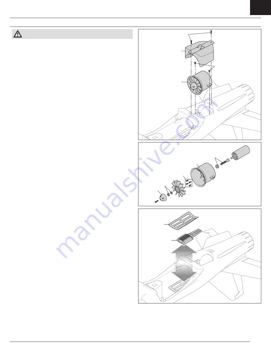
1.  Remove the two screws (A) from the fan unit cover (B) and pull the cover out 

of the fuselage.

2.  Remove the two screws (C) from the fan unit tabs.
3.  Pull the fan unit (D) out of the fuselage and disconnect the motor leads 

from the ESC.

4.  Remove the spinner (E) from the fan by removing the screw from the 

motor shaft adapter.

5.  Remove the nut and washer (F) to remove the fan (G) and motor shaft 

adapter (H).

6.  Remove the four screws (I) to remove the motor from the fan shroud (J).
7.  Carefully remove the plastic ESC cover (K). The cover is glued to the fuselage.
8.  Disconnect the throttle lead from the receiver and lift the ESC (L) from the 

fuselage, taking note of the routing of the power and throttle leads through 

the upper fuselage.

Assembly

• Assemble in reverse order.

• Correctly align and connect the motor wire colors with the ESC wires.

• Ensure the front of the rotor is installed facing the nose of the aircraft.

• A tool is required to tighten the nut on the rotor and collet.

• Ensure no wiring is pinched by any of the power components.

• Ensure the ESC cover is securely glued to the fuselage.

• Ensure the spinner is fully connected for safe operation.

Summary of Contents for Viper 70mm EDF

Page 1: ...Instruction Manual Bedienungsanleitung Manuel d utilisation Manuale di Istruzioni SAFE Select Technology Optional Flight Envelope Protection...

Page 2: ...al prior to assembly setup or use in order to operate correctly and avoid damage or serious injury As the user of this product you are solely responsible for operating in a manner that does not endang...

Page 3: ...eron 1 Flap 3 Servo Reversing Normal 4 Travel Adjust All Surfaces 100 Dual Rates High Rate Low Rate Aileron p 10mm q 10mm p 8mm q 8mm Elevator p 12mm q 12mm p 8mm q 8mm Rudder 14mm 14mm 8mm 8mm Flap T...

Page 4: ...rate values below 50 If lower rates are desired manually adjust the position of the pushrods on the servo arm NOTICE If oscillation occurs at high speed refer to the Troubleshooting Guide for more in...

Page 5: ...through the vertical tail and into the fuselage Do not over tighten the screws Horizontal Tail Installation 1 Connect both elevator servo connectors to the extensions in the fuselage labeled ELEV Feed...

Page 6: ...to install a different receiver ensure that it is at least a 6 channel full range sport receiver Refer to the manual of your chosen receiver for correct installation and operation instructions AR636A...

Page 7: ...tor noting the correct polarity The ESC will emit two sets of audible tones in succession indicating the programming status The first set of tones indicates the number of cells in the connected LiPo b...

Page 8: ...been switched OFF The throttle will not arm if the transmitter s throttle control is not put at the lowest position If problems are encountered follow the binding instructions and refer to the transm...

Page 9: ...p ensure a successful flight Fly the aircraft at these factory settings before making changes Depending on your experience level with electric ducted fan EDF jets program your transmitter to set the r...

Page 10: ...tend the landing gear and flaps The flaps will allow the aircraft to slow to a more manageable landing speed while still maintaining lift Elevator trim may be necessary to maintain level flight with t...

Page 11: ...aft adapter 5 Remove the nut and washer F to remove the fan G and motor shaft adapter H 6 Remove the four screws I to remove the motor from the fan shroud J 7 Carefully remove the plastic ESC cover K...

Page 12: ...ropeller Prop nut is too loose Tighten the prop nut Reduced flight time or aircraft underpowered Flight battery charge is low Completely recharge flight battery Propeller installed backwards Install p...

Page 13: ...6750 DX6 Transmitter Only MD2 G3 SPMR8000 DX8 Transmitter Only MD2 SPMR8100 DX8e 8CH Transmitter Only SPMR9910 DX9 Black Transmitter Only MD2 Problem Possible Cause Solution Control surface does not m...

Page 14: ...s a The aircraft control system and pilot skills have successfully demonstrated all maneuvers intended or anticipated prior to the specific event b An inexperienced pilot is assisted by an experienced...

Page 15: ...ice Contact Information section to speak with a Product Support representative Inspection or Services If this Product needs to be inspected or serviced and is compliant in the country you live and use...

Page 16: ...ID BRWDASRX15 This equipment has been tested and found to comply with the limits for a Class B digital device pursuant to part 15 of the FCC Rules These limits are designed to provide reasonable prot...

Page 17: ...and the Horizon Hobby logo are trademarks or registered trademarks of Horizon Hobby LLC The Spektrum trademark is used with permission of Bachmann Industries Inc All other trademarks service marks an...

Reviews: