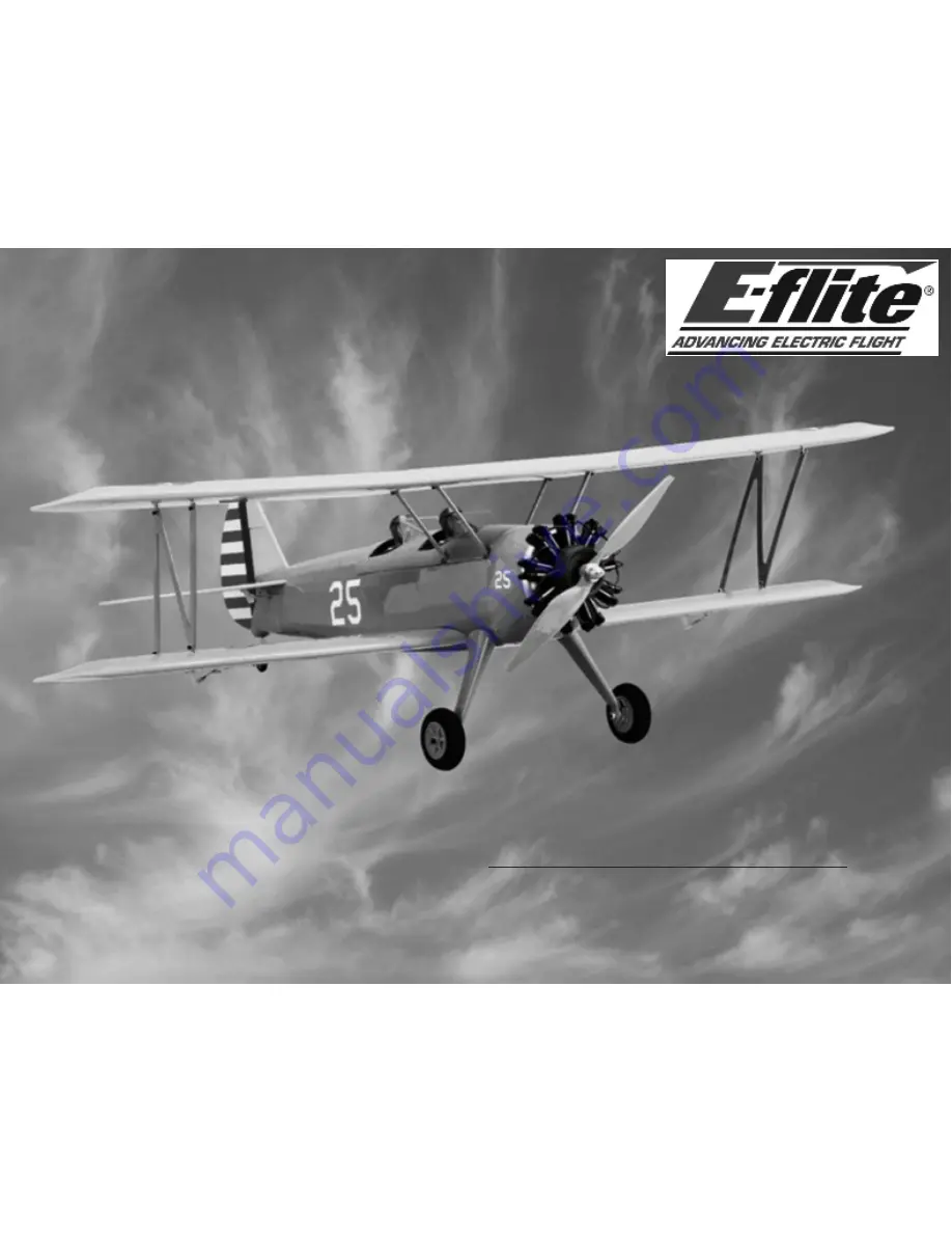
Stearman PT-17 15e ARF
Assembly Manual
Specifications
Wingspan
44 in (1117mm)
Length
35 in (889mm)
Wing Area
608 sq in (37.5 sq dm)
Weight with Battery
3.5–3.8 lb (1.5–1.7 kg)
Weight without Battery
3.1–3.3 lb (1.4–1.5 kg)
Pilots not included (available separately)


