background image



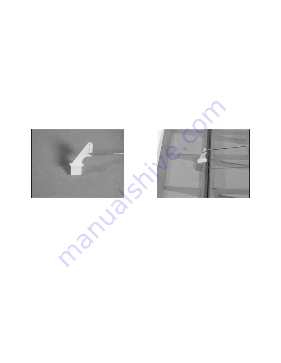
 4. Use a hobby knife to enlarge the inboard 

hole in the control horn to fit the 4" (100mm) long 
aileron pushrod wire.

 5. Repeat Steps 1 through 4 for the other 

wing panel.

 6. Use 6-minute epoxy to attach the control horn to 

the aileron. Attach the control horns for both the 
right and left ailerons at this time.

25

Summary of Contents for Mini FuntanaX

Page 1: ...Mini FuntanaX Assembly Manual...

Page 2: ...ce and Repairs 9 Inspection or Repairs 10 Warranty Inspection and Repairs 10 Non Warranty Repairs 11 Table of Contents Safety Precautions and Warnings 12 Landing Gear Installation 13 Outrunner Motor I...

Page 3: ...Specifications Wingspan 43 in 1092mm Length 40 5 in 1028mm Wing Area 447 sq in 28 8 sq dm Weight w o Battery 23 24 oz 652 680 g Weight w Battery 27 29 oz 765 822 g Using the Manual This manual is divi...

Page 4: ...et EFL2430 Main Landing Gear EFL2431 Fuselage Hatch EFL2432 Canopy EFL2433 Cowling EFL2434 Wheel Pants EFL2435 Wing Tube EFL2436 Side Force Generators Small Replacement Parts EFLA200 Micro Control Hor...

Page 5: ...ote We recommend the crystal free interference free Spektrum DX6 2 4GHz DSM 6 Channel System which includes a micro receiver and 4 sub micro servos Or Purchase Separately SPM6000 AR6000 DSM DuaLink 6...

Page 6: ...tric Prop EFLAEC302 EC3 Battery Connector Female 2 EFLC3005 Celectra 1 to 3 cell Li Po Charger This is a high power performance setup for strong 3D flights Optional Accessories EFLA110 Power Meter Req...

Page 7: ...ed it can cause serious bodily harm and damage to property Fly only in open areas preferably at AMA Academy of Model Aeronautics approved flying sites following all instructions included with your rad...

Page 8: ...izon Return of any goods by Purchaser must be approved in writing by Horizon before shipment a This warranty is limited to the original Purchaser Purchaser and is not transferable REPAIR OR REPLACEMEN...

Page 9: ...als Safety Precautions This is a sophisticated hobby Product and not a toy It must be operated with caution and common sense and requires some basic mechanical ability Failure to operate this Product...

Page 10: ...have internet access please include a letter with your complete name street address email address and phone number where you can be reached during business days your RMA number a list of the included...

Page 11: ...hecks as well as Visa MasterCard American Express and Discover cards If you choose to pay by credit card please include your credit card number and expiration date Any repair left unpaid or unclaimed...

Page 12: ...ections around your model as this margin will help to avoid collisions or injury Always operate your model in an open area away from cars traffic or people Avoid operating your model in the street whe...

Page 13: ...L R 1 3 4 45mm wheel 2 4 40 x 3 8 machine screws 2 4 black washers 2 4 40 nut 2 4 40 locknut 2 4 40 x 1 machine screw 2 4 steel washers 4 2mm x 6mm wood screws 2 Required Tools and Adhesives Phillips...

Page 14: ...w Secure the bolt with a 4 40 locknut while using needle nose pliers to hold the head of the bolt inside the pant 4 Repeat Steps 2 and 3 for the remaining wheel and wheel pant 2 Slide the 4 40 x 1 mac...

Page 15: ...driver Phillips 0 Note This section covers the installation of the recommended Park 480 Outrunner motor The holes in the firewall match the mounting pattern of the X mount 1 Attach the supplied alumin...

Page 16: ...p adapter for outrunner motor Electronic speed control Required Tools and Adhesives Screwdriver Phillips 0 Cardstock Masking tape Hook and loop material Drill Drill bit 1 16 1 5mm 5 64 2mm Important I...

Page 17: ...to the inside of the fuselage using hook and loop material Actual ESC location may vary but proper air flow and cooling is important 2 Connect the speed control to the radio system and motor battery...

Page 18: ...ide the cowling onto the fuselage Install the propeller adapter onto the Outrunner shaft You may need to ream out the hole on your prop hub to fit the prop adapter shaft at this point Slide the propel...

Page 19: ...the cowl using four 2mm x 8mm sheet metal screws Snap the spinner cone onto the spinner backplate once the cowl is secure Hint Use thin CA to harden the holes drilled into the cowl mounting tabs This...

Page 20: ...nd Adhesives T pins Thin CA Drill Paper towel Drill bit 1 16 1 5mm 1 Locate the positions for the hinges Drill a 1 16 2mm hole in the center of each slot of both the wing and aileron This creates a tu...

Page 21: ...s The CA must be allowed to soak into the hinge to provide the best bond Using accelerator will not provide enough time for this process 3 Slide the aileron into position Check to make sure it can mov...

Page 22: ...he hinges are secure and cannot be pulled apart Use caution when gripping the wing and aileron to avoid crushing the structure 5 Work the aileron up and down several times to work in the hinges and ch...

Page 23: ...ervo EFLRS75 2 Required Tools and Adhesives Hobby knife 6 minute epoxy 6 150mm servo extension 2 String Phillips screwdriver small 1 Attach a 6 150mm servo extension Use string to secure the servo lea...

Page 24: ...2 Place the servo in the wing Guide the servo lead out through the opening at the wing root 3 Secure the aileron servo using the screws provided with the servo 24...

Page 25: ...he control horn to fit the 4 100mm long aileron pushrod wire 5 Repeat Steps 1 through 4 for the other wing panel 6 Use 6 minute epoxy to attach the control horn to the aileron Attach the control horns...

Page 26: ...your servos to provide the greatest amount of throw 8 Turn on the radio system and center the aileron trim and stick Make sure the aileron servo is operating properly using the transmitter Slide the p...

Page 27: ...her silver 2 4 40 x 1 2 machine screw 2 Wing fairing 2 Fairing spring Required Tools and Adhesives Hex wrench 3 32 6 minute epoxy Pliers 1 Slide the wing tube into a wing panel 2 Remove the hatch from...

Page 28: ...ws with 4 washers silver using a 3 32 hex wrench 4 Test fit the wing fairing filets into position against the wing You may need to loosen the screw holding the wing in place to install the fairing Ins...

Page 29: ...ght against the wing while the epoxy cures Note The fairing may not fit tight against the fuselage at this time This will be addressed once both fairings have been installed 6 Repeat Steps 3 through 5...

Page 30: ...hesives Hobby knife Felt tipped pen Ruler T pins Thin CA 1 Hinge the elevator and stabilizer using the same process as described in Aileron Hinging Use 6 hinges for this process 2 Position the stabili...

Page 31: ...he stab tip to the wing tip Adjust the stab until the measurements are equal A A A A 4 View the airframe from the rear and make sure the wing and stab are parallel If not lightly sand the stab saddle...

Page 32: ...d bottom of the stabilizer 6 Use a sharp hobby knife to cut the covering slightly inside the lines drawn Be very careful not to cut into the underlying wood as this will weaken the stab and cause it t...

Page 33: ...eck the alignment and make sure everything lines up Wick Thin CA into the joint between the fuselage and stabilizer Make sure to glue both top and bottom Do not use accelerator to allow the CA to wick...

Page 34: ...sandpaper 1 Roughen the tail wheel assembly using medium grit sandpaper Use 6 minute epoxy to glue the tail wheel assembly into the rudder 2 Hinge the rudder and fin using the same process as describ...

Page 35: ...of the fin using the same technique used for the stabilizer 4 Position the fin back onto the fuselage Use a square to check the alignment between the fin and stabilizer Lightly sand the bottom of the...

Page 36: ...Micro control horn w backplate 2 5 3 4 145mm pushrod wire 2mm x 4mm screw 2 4 1 2 115mm pushrod wire Micro control connector w retainer 2 Servo 2 18 457mm servo extension 2 6 1 2 carbon rod 2 6 1 2 c...

Page 37: ...the hardware provided with the servo 2 Use a hobby knife to enlarge the inboard hole in one of the remaining control horns Attach the 4 1 2 115mm pushrod wire to the control horn 3 Attach the micro co...

Page 38: ...shrod wire through the connector With the radio on and elevator trim centered center the elevator Secure the elevator pushrod wire using the 2mm x 4mm screw and a small Phillips screwdriver 5 Repeat S...

Page 39: ...e fuselage and stabilizer Make notches in the stabilizer and fuselage for the rods to rest in Secure the rods using 6 minute epoxy Note Make sure the rods are positioned so they don t interfere with t...

Page 40: ...2 Felt tipped pen Canopy glue 1 Plug in the elevator and rudder servos and ESC into the receiver Mount the receiver to the inside of the fuselage using hook and loop material Route the antenna wire th...

Page 41: ...tipped pen to trace the outline of the canopy onto the fuselage 3 Use medium grit sandpaper to roughen the covering 1 8 3mm inside the line drawn Also roughen the outside 1 8 3mm of the canopy Clean...

Page 42: ...aircraft fully assembled install the battery into the battery compartment Secure the battery using the hook and loop tape and a hook and loop strap Note Place a piece of hook and loop tape on the bot...

Page 43: ...o the wing tips using four 4 40 x 1 2 socket head screws Add the plywood disks between the side force generators and the wing tip to prevent the aileron from rubbing against the side force generator N...

Page 44: ...he movement of the elevator with the radio system Moving the elevator stick down will make the airplane elevator move up 3 Use a ruler to adjust the throw of the elevator ailerons and rudder Adjust th...

Page 45: ...ing the aircraft for flight is properly balancing the model Caution Do not inadvertently skip this step The recommended Center of Gravity CG location for the Mini FuntanaX is 3 3 4 95mm behind the lea...

Page 46: ...hould be able to walk 30 paces approximately 100 feet away from your airplane and still have complete control of all functions If not don t attempt to fly Have your radio equipment checked out by the...

Page 47: ...fly Have your radio equipment checked out by the manufacturer Note Keep loose items that can get entangled in the propeller away from the prop These include loose clothing or other objects such as pen...

Page 48: ...apable of anything you want to put it through Flying high alpha is very easy and you will find the model exhibits very nice control authority in all respects Rolls are very crisp and precise on either...

Page 49: ...Building and Flying Notes 49...

Page 50: ...al flying behind the flight line is prohibited GENERAL 1 I will not fly my model aircraft in sanctioned events air shows or model flying demonstrations until it has been proven to be airworthy by havi...

Page 51: ...arters Documents of agreement and reports may exist between 1 two or more AMA Chartered Clubs 2 AMA clubs and individual AMA members not associated with AMA Clubs or 3 two or more individual AMA membe...

Page 52: ...9513 2006 Horizon Hobby Inc 4105 Fieldstone Road Champaign Illinois 61822 877 504 0233 horizonhobby com E fliteRC com...

Reviews: