


8
S1
D1
I
U
D2
S2
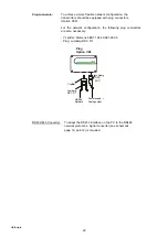
5. Push-Buttons
for calibration
purposes
2. RS232/RS485
3. Fitting of the
Network Chip
6. Diagnosis LEDs
4. Display
1. Current/voltage output
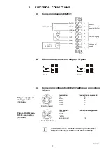
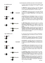
1.
Current/voltage output:
When the device will be switched from current to voltage
output signals using the configuration software supplied,
then two jumpers must also be positioned as follows.
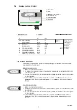
for current signals:
for voltage signals:
2.
RS232/RS485:
For the transition from RS232 to RS485 (network
operation) these jumpers must be removed.
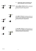
3.
Fitting of the network chip:
For refitting to RS485, an IC must be used (available as
an option). The notch on the chip must match the
receiver slot!
4.
Display:
These pinboards are determined for connecting the
display module.
5.
Push-Buttons for calibration purposes: see Hardware, chapter 7 “Humidity/Temperature calibration”
6.
Diagnosis LEDs:
see Harware, chapter 7 "Humidity/Temperature calibration,"
and chapter 8.3 "Self diagnosis and error messages"
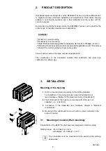
5.1
Circuit board
After removal of the housing cover, the following operating components on the circuit board
may be accessed for adaptation of the transmitter to the desired configuration.
5.
OPERATING COMPONENTS
I
U
I
U
Hardware


