background image

Document:  

Date

Created By: 


ECO# 

LPN00522X0001A1 

  2018-3-03

TMT 

  002362

INSTALLATION INSTRUCTIONS

E-TFP LED Flat Panel  

www.e-conolight.com      |     888.243.9445     |     FAX: 262.504.5409

CAUTIONS

IMPORTANT SAFEGUARDS

When using electrical equipment, basic safety 

precautions should always be followed including the 

following:

READ AND FOLLOW ALL SAFETY 

INSTRUCTIONS

1.  DANGER

- Risk of shock- Disconnect power before 

installation.

DANGER

 – Risque de choc – Couper l’alimentation 

avant l’installation.

2.  Caution

 - Risk of Fire. 

Attention

 - Risque D’incendie

3.  This luminaire must be installed in accordance with the 

nec or your local electrical code. If you are not familiar 

with these codes and requirements, consult a qualified 

electrician. 

Ce produit doit être installé conformément à nec ou votre 

code électrique local. Si vous n’êtes pas familier avec ces 

codes et ces exigences, veuillez contacter un électricien 

qualifié.

4.  Suitable for damp locations. 

Convient aux emplacements humides.

5.  Min 90°C supply conductors. 

Les fils d’alimentation 90°C min.

6.  Inherently protected. 

Protection inherente.

7.  Type IC. Vapor barrier must be suitable for 90°C. 

Type IC. Le pare-vapeur doit convenir pour 90°C.

SAVE THESE INSTRUCTIONS FOR 

FUTURE REFERENCE


1. 

Locate desired fixture location in ceiling grid.

2. 

Remove existing ceiling panel at chosen location. Remove 
adjacent ceiling panel to allow for wiring access from above.

3. 

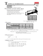
Place fixture into T-bar ceiling grid. Bend clips on top of fixture up 
and rotate out to engage with T-bar support grid. See 

Figure 1. 

Secure fixture to grid in compliance with state and local codes.

4. 

Remove screw on driver wiring chamber and remove cover. Set 

screw and cover aside to be reinstalled later.

5.  Remove appropriate 1/2" knockout(s) to allow for entry of supply 

wiring into wiring chamber.

6. 

Make wiring connections per the 

Fixture Wiring

 section.

NOTE:

• 

Terminal blocks in driver wiring chamber will accommodate 

12-20 AWG solid or stranded leads for supply and 18-24 

AWG solid or stranded leads for dimming.

• 

For dimming connections (if used) use Class 1 wiring 

methods only.

7. 

Reattach cover of wiring chamber with screw that was removed in 

Step 4 above.

8. 

Replace adjacent ceiling panel removed in Step 2.

INSTALLATION

FIGURE 1

1x4

2x2

2x4

Summary of Contents for E-TFP Series

Page 1: ... C min 6 Inherently protected Protection inherente 7 Type IC Vapor barrier must be suitable for 90 C Type IC Le pare vapeur doit convenir pour 90 C SAVE THESE INSTRUCTIONS FOR FUTURE REFERENCE 1 Locate desired fixture location in ceiling grid 2 Remove existing ceiling panel at chosen location Remove adjacent ceiling panel to allow for wiring access from above 3 Place fixture into T bar ceiling gri...

Page 2: ...armful interference in which case the user will be required to correct the interference at his own expense CAN ICES 005 A NMB 005 A FCC NOTICE Class A Fixture is equipped with universal volt driver 120 277V ie 120V 208V 240V or 277V PHASE TO NEUTRAL WIRING 120 277V 1 Connect supply ground to fixture ground green lead 2 Connect supply common to fixture neutral AC N terminal on terminal block in dri...

Page 3: ...IC Le pare vapeur doit convenir pour 90 C GUARDE ESTAS INSTRUCCIONES PARA REFERENCIA FUTURA 1 Determine la ubicación deseada para la luminaria en la rejilla del techo 2 Retire el panel de techo existente en la ubicación seleccionada Retire el panel de techo contiguo para acceder al cableado desde arriba 3 Coloque la luminaria en la barra en T de la rejilla del techo Doble los clips de la parte sup...

Page 4: ...o está equipado con un controlador universal de voltaje 120 277 V es decir 120 V 208 V 240 V o 277 V CABLEADO DE FASE A NEUTRO DE 120 277 V 1 Conecte el cable de puesta a tierra del suministro a la tierra de la luminaria verde 2 Conecte el cable neutro del suministro al neutro AC N de la luminaria en el bloque de terminales en la caja de conexiones 3 Conecte el cable de suministro de corriente del...

Page 5: ...adjacent afin de permettre l accès du câblage depuis le haut 3 Placez le luminaire dans la grille de plafond avec barre en T Pliez vers le haut les attaches situées au haut du luminaire et faites pivoter pour qu elles s engagent avec la grille de support avec barre en T Voir Figure 1 Fixez le luminaire sur la grille en conformité avec le codes provinciaux et locaux 4 Enlevez la vis située sur la c...

Page 6: ...opres frais CAN ICES 005 A NMB 005 A AVIS DE LA FCC Classe A Le luminaire est équipé d un système d entraînement de tension universelle de 120 à 277 volts c est à dire 120 V 208 V 240 V ou 277 V CÂBLAGE PHASE AU NEUTRE 120 277 V 1 Raccorder l alimentation de mise à la terre de l alimenta tion à celui vert du luminaire 2 Raccorder l alimentation commune à la borne neutre AC N du luminaire sur le bl...

Reviews: