background image

SV-D600 and SV-D900 Operation 


3-2 


SkyView SE 

Pilot’s User Guide 

- Revision B 

\


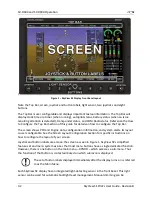
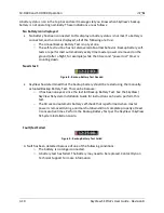
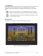
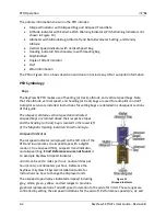
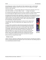
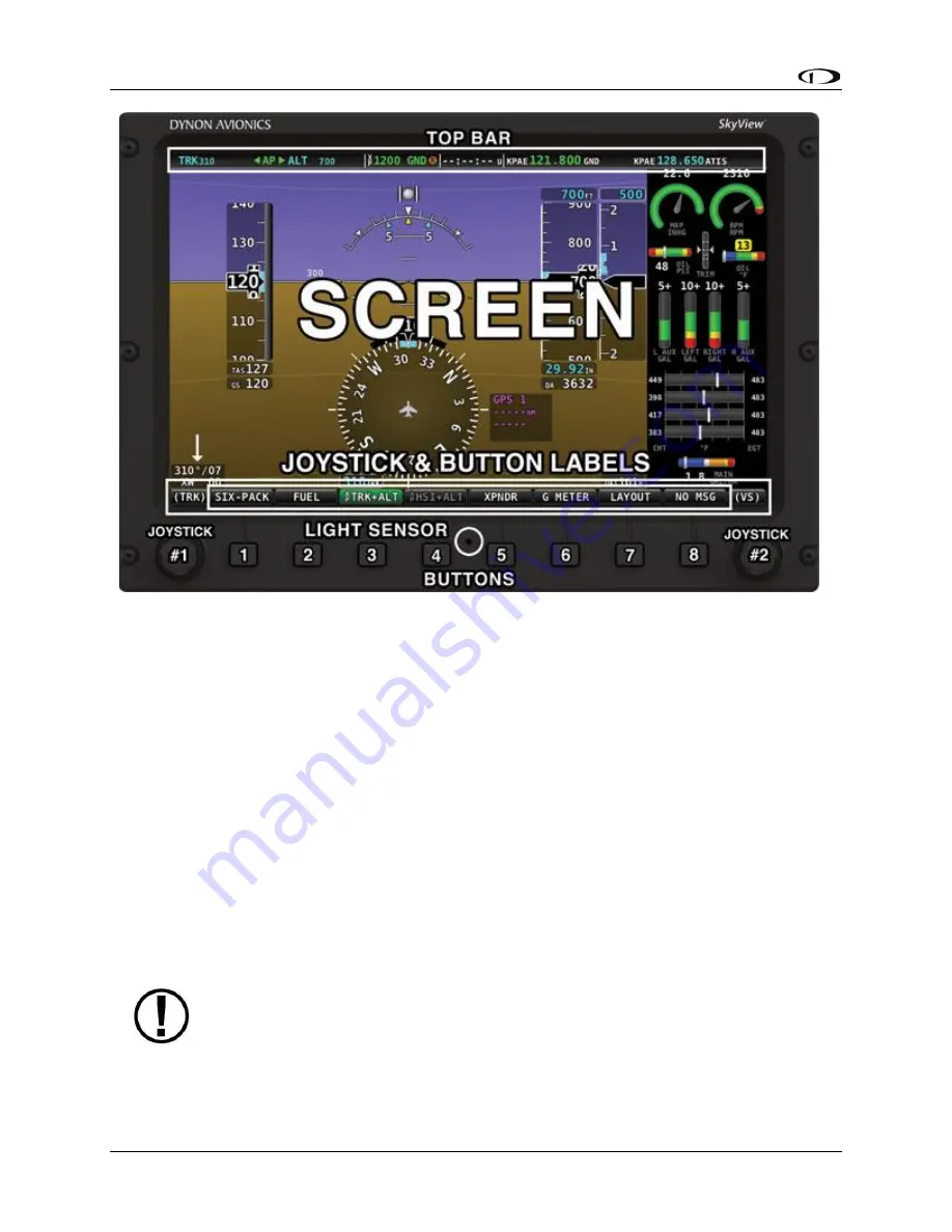
Figure 1 

 SkyView SE Display Front Bezel Layout 

Note the Top Bar, screen, joystick and button labels, light sensor, two joysticks and eight 
buttons. 

The Top Bar is user configurable and displays important textual information. The Top Bar will 
display clock time or a timer (when running), autopilot status, battery status (when an issue 
requiring attention is detected), transponder status, and COM Radio status. Reference the How 
to Configure the Top Bar 
Section of this guide for details on how to configure the Top Bar. 

The screen shows PFD and Engine data, configuration information, and system alerts. Its layout 
is user configurable. See the Screen Layout Configuration Section for specific instructions on 
how to configure the layout of your screen. 

Joystick and button labels are also on the screen as seen in Figure 1. 

SkyView SE’s simplified 

feature set and menu system assures that most menu buttons have a single dedicated function. 
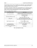
However, there is one button on the main menu 

 XPNDR 

 which accesses a sub-menu. Thus 

the function of that button is 

contextual based on which submenu is displayed.


The set of button labels displayed immediately after the display turns on is referred 
to as the 

Main Menu

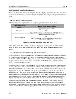
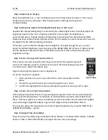
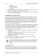
Each SkyView SE display has an integrated light-detecting sensor in the front bezel. This light 
sensor can be used for automatic backlight level management. Manual dimming can be 

Summary of Contents for SkyView SE

Page 1: ...t be installed into traditional FAA Part 23 and similarly type certificated aircraft Document 102824 000 Revision B For use with software version 15 4 January 2020 Copyright 2009 2020 by Dynon Avionic...

Page 2: ...net forum http newsletter dynonavionics com Dynon s email newsletter http twitter com dynon Dynon Avionics is on Twitter Copyright 2008 2016 Dynon Avionics Inc All rights reserved No part of this manu...

Page 3: ...Y FROM STATE TO STATE AND IN COUNTRIES OTHER THAN THE USA IN NO EVENT SHALL DYNON AVIONICS BE LIABLE FOR ANY INCIDENTAL SPECIAL INDIRECT OR CONSEQUENTIAL DAMAGES WHETHER RESULTING FROM THE USE MISUSE...

Page 4: ...Guide Revision B v Revision History Revision Revision Date Description A April 2016 Initial release B January 2020 Added the SV COM X25 COM radio to Sections 2 3 and 8 Table 1 SkyView SE Pilot s User...

Page 5: ...OM C25 2 6 SV COM X25 2 6 SV COM X83 2 6 SV INTERCOM 2S 2 6 SV KNOB PANEL 2 6 SV KNOB DIMMER 2 6 SV BUTTON LEVEL 2 6 3 SV D600 and SV D900 Operation 3 1 Screen Synchronization 3 1 Display Bezel Layout...

Page 6: ...Radio Operation 8 1 Top Bar COM Radio Status Overview 8 1 Using your COM Radio 8 2 Loading Airports to the SkyView SE Com Radio 8 6 Using the TWR ATIS GND and ATC Buttons 8 8 Aviation Database 8 8 Oth...

Page 7: ...ny field user serviceable parts Units found to have been taken apart may not be eligible for repair under warranty Additionally once a Dynon Avionics unit is opened up it is not considered airworthy a...

Page 8: ...f wiring diagrams photos and other types of electronic files www dynonavionics com videos is an online video database including a series of SkyView SkyView SE training and feature videos These videos...

Page 9: ...known At the same time many optional SkyView components required for more complex aircraft operations are not supported in SkyView SE Excluding support for these components allows the screen and pilot...

Page 10: ...nt data network In fact SkyView has the ability to annunciate wiring issues as they are discovered often while preserving full system functionality until full troubleshooting can be performed on the g...
Page 11: ...SV ADAHRS 201 The SV ADAHRS 200 and SV ADAHRS 201 are identical in performance and are designed to work together as a redundant ADAHRS solution An SV ADAHRS 200 must be installed in your SkyView SE s...

Page 12: ...ing GPS ground speed will be used as an attitude aid You will see a GPS ASSIST annunciation on the primary flight display when this is the case Compass Accuracy Effects on Synthetic Vision Map Perform...

Page 13: ...ically for use with SkyView Either one can supply GPS data in NMEA format and automatically set the time on SkyView SE The SV GPS 2020 is an ADS B Out 2020 compliant GPS position source When included...

Page 14: ...modules the SV COM PANEL and the SV COM T8 The SV COM X83 has 8 33 kHz spacing and is able to tune frequencies by integrating with SkyView SE s aviation database SkyView SE can support two SkyView CO...

Page 15: ...important information between them Actions such as setting baro bugs engaging the autopilot or acknowledging warnings only need to be performed on one display or control panel to be reflected across t...

Page 16: ...onfiguration information and system alerts Its layout is user configurable See the Screen Layout Configuration Section for specific instructions on how to configure the layout of your screen Joystick...

Page 17: ...ferences Joystick and Button Operation Joysticks and buttons are used for various functions including powering the unit on and off entering and navigating menus and adjusting values Operation Basics J...

Page 18: ...e a joystick selection OR a button push the correct choice will be apparent Menu Navigation After the display turns on you will see a screen similar to the one in Figure 1 This guide refers to the lab...

Page 19: ...ROMETER Menu to select INHG MBAR or MMHG Table 3 is a summary of menu navigation Desired Menu Action User Action Enter the Setup Menu Simultaneously press and hold buttons 7 and 8 if airspeed is great...

Page 20: ...the battery charge depending on whether or not the aircraft is in flight This feature minimizes backup battery discharge when on the ground and master external power is shut off normally It also redu...

Page 21: ...r the Joystick Function Menu These menus are used to specify which bug or parameter that joystick adjusts if turned For example joystick 1 could be set to adjust the heading bug and joystick 2 could b...

Page 22: ...isplays Each display in the system can also have its own layout This section tells you how to configure the display s in your SkyView SE system SkyView SE displays only display data from connected mod...

Page 23: ...ally connected to This ensures that the display has a fully charged backup battery in case of emergency Charging a completely discharged battery may take up to 4 hours To conserve your aircraft batter...

Page 24: ...is counting down Needs test Figure 8 Backup Battery Test Needed SkyView has determined that the backup battery should be tested using the manually actuated Backup Battery Test This can be because o I...

Page 25: ...ions for adjusting bugs SkyView s PFD requires data from an SV ADAHRS 200 201 module If installed SkyView s heading will be determined by the SV MAG 236 Remote Magnetometer The heading track altitude...

Page 26: ...g bugs are detailed in subsequent sections of this guide The airspeed altitude vertical speed and indicated airspeed bugs are located above their respective tapes and the heading or track bug is locat...

Page 27: ...6 seconds have passed True airspeed TAS is digitally displayed at the bottom of the airspeed tape If configured with a GPS Ground Speed GS is also displayed under the True Airspeed In some aircraft Vn...

Page 28: ...age in the In Flight Setup Menu IN FLIGHT SETUP MENU FLIGHT ANGLE PITCH ADJUST The pitch may be adjusted to a maximum of 20 degrees The extended zero pitch line features heading markers every 30 degre...

Page 29: ...View altimeter The altitude tape displays 200 units above and below the current altitude digital readout Each tick represents 25 units with every 50 unit tick drawn slightly longer to differentiate th...

Page 30: ...ent GPS Altitude After the BARO is synchronized a GPSALT message will appear in the altimeter box on the PFD In the Air Adjusts the altimeter to the standard pressure setting i e 29 92 in Hg 1013 mbar...

Page 31: ...hether or not the autopilot is engaged See the SkyView SkyView SE System Installation Guide for details on how to configure the altitude alerter Vertical Speed Indicator The vertical speed indicator V...

Page 32: ...ng compass rose magnetic heading digital display turn rate indicator ground track GPS pointer heading bug and heading bug digital display Figure 16 is an example SkyView SE Magnetic Heading Indicator...

Page 33: ...ck to adjust the heading track bug Note that while the heading track bug is changing its display window lights up in cyan to draw your attention to it You can synchronize the heading track bug to the...

Page 34: ...craft towards the CDI needle you reduce your deviation Wind Vector Wind vector information is located just above the OAT display on the PFD The winds aloft arrow indicates the wind direction relative...

Page 35: ...its can be set to degrees Fahrenheit or degrees Celsius Reference the SkyView SkyView SE System Installation Guide for instructions on how to change the displayed units If OAT is not valid i e disconn...

Page 36: ...way Figure 25 SIX PACK Display To turn on the six pack press Button 1 SIX PACK on the main menu The button background will turn grey denoting that feature is turned on All the same information is disp...

Page 37: ...ADAHRS Parameters that are continuously cross checked include attitude pitch and roll magnetic heading G Meter turn coordinator slip skid ball airspeed and altitude Figure 26 ADAHRS Cross Checking Di...

Page 38: ...uide Revision B Figure 27 ADAHRS Cross Check Comparison Once you have determined which ADAHRS is incorrect press DISABLE to tell SkyView SE not to use it for the duration of the flight Figure 28 ADAHR...

Page 39: ...an ADAHRS a red warning and ADAHRS CROSS CHK ERROR alert will persist in the Message Alert Area above button 8 To go back to the ADAHRS comparison screen to disable an ADAHRS see the below instructio...

Page 40: ...ext powered up simply highlight it with the joystick and press the DISABLE button To see the same comparison screen that is presented when a cross check error occurs press the COMPARE button at the bo...

Page 41: ...de for further information about G Meter configuration Top Bar The Top Bar contains a clock as well as status information for Autopilot Transponder SkyView SE Backup Battery and COM Radio Clock behavi...

Page 42: ...flight display These knobs behave exactly like the joystick knobs on a SkyView SE display do when they are set to these functions turn them to adjust the value they control Press and hold them to syn...

Page 43: ...uld have been configured during installation The appearance of the 20 and 50 Engine Pages are not scaled down versions of the 100 Engine Page They are unique layouts and must be laid out individually...

Page 44: ...enter their red ranges In other words yellow caution ranges for engine parameters do not trigger alerts Yellow caution ranges however are visually annunciated via yellow highlighting on the Engine Pa...

Page 45: ...erature behave in the following ways Tachometer for Rotax 912 When OIL TEMP 120 F the TACHOMETER displays these ranges 0 1400 and 4000 6000 RPM in RED 1400 1800 and 2500 4000 RPM in YELLOW 1800 2500 R...

Page 46: ...SkyView SE uses the presence of significant airspeed or GPS speed to decide whether the aircraft is flying This timer can only be reset or adjusted in the Aircraft Information menu within SkyView SE...

Page 47: ...h respect to the speed it is traveling over the ground this also can be displayed as MI GAL KT GAL KM LTR The Fuel Range info item displayed as RANGE displays the distance the aircraft can travel at i...

Page 48: ...ned fuel state See the SkyView SkyView SE System Installation Guide for information about how to set this value Press MATCH to have SkyView SE automatically add subtract the appropriate amount of fuel...

Page 49: ...y It is critical to note that only the Class 1 version SV XPNDR 261 meets the requirements for an ADS B Out transmitter under the 2020 mandate Regardless of your aircraft s performance you must use th...

Page 50: ...nd GND modes reflected in the transponder status in the top bar using a combination of GPS and air data changes d ON The transponder will respond to all interrogations but altitude reporting is suppre...

Page 51: ...main highlighted in this menu and GND is annunciated in the transponder status area in the Top Bar When the transponder is in ground mode pressing GND again will turn ground mode off and put the trans...

Page 52: ...1 262 setting BARO to 29 92 will display the pressure altitude being transmitted to the transponder in the normal SkyView SE altitude display on the PFD page ADS B OUT Transmissions If SkyView SE has...

Page 53: ...If you are operating within the United States there may be a service bulletin which applies to your transponder please see the Service Bulletins section of our website for more information Flight Plan...

Page 54: ...rcuit breaker or fuse on in the aircraft will completely inhibit the Autopilot servos from controlling the airplane However SkyView SE does continuously look for the presence of powered up servos even...

Page 55: ...which the autopilot is providing guidance Flashes for 10 seconds when an armed mode is sequenced and has become the active mode o Armed Mode or The mode to which the autopilot will automatically tran...

Page 56: ...ion combined with a trim request However Auto Trim will not attempt to actuate the trim controllers during a slip Figure 44 Pitch Slip Trim Nose Up Indicator Roll Trim Indicators When the autopilot is...

Page 57: ...Displayed when the disconnect switch is held down to engage the autopilot The behavior upon release is different for Simplified and Expert Autopilot Control schemes See the Simplified and Expert Cont...

Page 58: ...he aircraft has reached its maximum or minimum airspeed limits as configured when the Autopilot was set up When either of these indications is displayed the autopilot will not pull or push on the pitc...

Page 59: ...n 3 TRK ALT This engages the autopilot in Track Hold and Altitude Hold modes simultaneously when both pitch and roll servos are installed If only a single servo is installed pressing Button 3 will eng...

Page 60: ...ilot is outside of its allowable engagement speed ranges LEVEL Requires optional SV BUTTON LEVEL If an SV BUTTON LEVEL shown at right is installed and properly configured pressing the SV BUTTON LEVEL...

Page 61: ...direction that the aircraft was flying in the moment before the autopilot was engaged After the autopilot is engaged change the track you want the autopilot to fly by adjusting the TRK bug HSI GPS GPS...

Page 62: ...de in vertical speed mode The rate of climb or descent during autopilot controlled changes in altitude is governed by the VS vertical speed bug When the autopilot is engaged and a new altitude is sele...

Page 63: ...ange The roll axis resumes tracking its HSI source The Control Wheel Steering feature can be enabled and disabled via the Autopilot Setup Menu See the SkyView SkyView SE System Installation Guide for...

Page 64: ...uttons Of course you can also spin frequencies in the old fashioned way when you re feeling nostalgic or are following ATC instructions COM Control Panel Overview The SV COM C25 X25 X83 has a dedicate...

Page 65: ...hey may not power up at the same time as your SkyView SE displays Press and hold the Volume Knob Power Button to manually turn the SkyView SE COM Radio off and on Volume Use the volume knob to adjust...

Page 66: ...nly receives radio stations that have active transmissions on them However you may wish to override this feature to hear a distant radio station or to help set the radio volume To listen to the active...

Page 67: ...quency The active frequency always receives priority This is true even if dual watch is listening to a continuous broadcast on the standby frequency For example if ATIS is on standby and tower is on a...

Page 68: ...you start with is 123 450 turning the large knob will change the numbers before the decimal 123 while the small knob will adjust the numbers after the decimal 450 Press the dual concentric knob on th...

Page 69: ...atically tune those frequencies to the standby location for that airport Loading Airports via the COM Control Panel By Nearest Press the APT button once NRST APT is displayed on the control panel and...

Page 70: ...y location Figure 85 Figure 86 By A Z 0 9 Character Entry Press the APT button twice Figure 87 Figure 88 Use the dual concentric knob to type an airport identifier Note that this search is limited to...

Page 71: ...standby frequency Repeated presses of these buttons will cycle through all available frequencies of that type for example busy airports may have multiple tower frequencies TWR Tunes tower UNICOM and...

Page 72: ...abase to a USB memory stick Reference the Loading Databases section below of this guide for instructions on how to import the file onto a SkyView SE display Aviation data is updated every 28 days Once...

Page 73: ...to place the Jeppesen data on the USB memory stick that will be used to load the data onto SkyView SE If you manually copy Jeppesen data onto a USB memory stick it will not load onto your SkyView SE...

Page 74: ...el will display NoSV The control panel annunciates this condition in the following way Figure 93 No SkyView mode You may see this annunciation as your SkyView SE displays first power up as they take l...

Page 75: ...8 Without GPS position airport loading and TWR ATIS GND ATC will not be available You may see this annunciation as SkyView SE starts up or when the aircraft does not have GPS reception for example whe...

Page 76: ...ve more than one COM radio that is capable of communicating with SkyView SE only the primary COM radio s status information will be displayed in the Top Bar Additionally only the primary radio will re...

Page 77: ...ata source such as an EMS module fails or a red X may overlay a single widget if a single engine sensor fails or is not connected For example the PFD would look like Figure 101 if all ADAHRS in the sy...

Page 78: ...ledged Caution Alert condition still present Solid Persistent but acknowledged Warning Alert condition still present Solid No active alerts or messages no color Table 7 Notification Types Whenever a n...

Page 79: ...sage Window The Message Window provides more detailed information about messages and alerts Press the rightmost button under the Message Notification Area to display the Message Window Figure 103 Mess...

Page 80: ...ending on how SkyView SE is configured Instructions for adjusting this behavior are discussed in the SkyView SkyView SE System Installation Guide If new messages or alerts are triggered while the Mess...

Page 81: ...fication Area Alert severity Description Warning ADAHRS FAIL ADAHRS failure ADAHRS Cross Check Error ADAHRS CROSS CHK ERROR Displayed after an ADAHRS cross check error was announced in a multi ADAHRS...

Page 82: ...backup battery connected to this display is low Warning SKYNET POWER FAULT A fault has been detected in the wires that provide power to SkyView SE Network devices Warning AUDIO SUBSYSTEM FAIL SkyView...

Page 83: ...236 is not calibrated Caution COMPASS FAIL The SkyView SE Remote Magnetometer has failed or is no longer communicating via SkyView Network Caution NEED USER AOA CAL AOA is not properly calibrated Cau...

Page 84: ...ile in flight IAS has become invalid likely due to icing or obstruction and all GPS sources have failed The attitude indication should be considered unreliable Caution CPU TEMP CRITICAL The display in...

Page 85: ...View SE components are not all running the same software version Message TAIL MISMATCH Tail numbers differ between SkyView SE displays settings will not properly synchronize Message XPNDR NOT IN ALT M...

Page 86: ...been annunciating this visually on the display for at least 30 seconds This alert is played a maximum of once every 30 seconds Trim Down None n a The autopilot requires nose down trim to maintain cont...

Page 87: ...is descending through the configured minimum warning speed Table 8 Messages Alerts and Audio Alert Details STANDBY NETWORK ERROR Explained The SkyView Network that connects your ADAHRS s EMS module A...

Page 88: ...lerting is enabled it enables a progressive tone that increases in intensity as AOA increases It is similar in nature to a conventional reed type aircraft stall warning sound although it is much more...

Page 89: ...SkyView SE Pilot s User Guide Revision B 10 1 10 Appendix A SkyView SE System Specifications See the current revision of the SkyView SkyView SE System Installation Guide...

Page 90: ...to be licensed as a whole at no charge to all third parties under the terms of this License c If the modified program normally reads commands interactively when run you must cause it when started runn...

Page 91: ...file to most effectively convey the exclusion of warranty and each file should have at least the copyright line and a pointer to where the full notice is found one line to give the program s name and...

Page 92: ...SING IN ANY WAY OUT OF THE USE OF THIS SOFTWARE EVEN IF ADVISED OF THE POSSIBILITY OF SUCH DAMAGE _________________ Magnetic Heading Calibration Routine contains portions of the following software Cop...

Reviews: