Dynon Avionics FlightDEK-D180 Installation Manual Download Page 24

Transducer Installation 


If you notice fluctuations on the manifold pressure reading on the FlightDEK-D180, you may 
need to install a restrictor with a small hole inline between the sensor and the head where the 
manifold pressure line is split off.  

Oil Pressure Sensor 

The FlightDEK-D180 supports several oil pressure sensor installations. The Dynon-supplied 
sensor and the Rotax and Jabiru pre-installed sensors are the most common.  

DYNON-SUPPLIED OIL PRESSURE SENSOR 

First, mount the oil pressure sensor to a fixed location 
using an Adel clamp (see picture at lower right) or other 
secure method. The oil pressure sensor must 

not

 be 

installed directly to the engine due to potential vibration 
problems. Dynon Avionics’ sensor is supplied with a 
1/8” NPT pipe thread fitting. An adapter might be necessary 
for some engines. Please see the manual supplied by the 
engine’s manufacturer. You must use appropriate pipe fitting 
adapters and 

ensure that the case of the sender has a 

connection to ground. 

This is critical for functionality.  
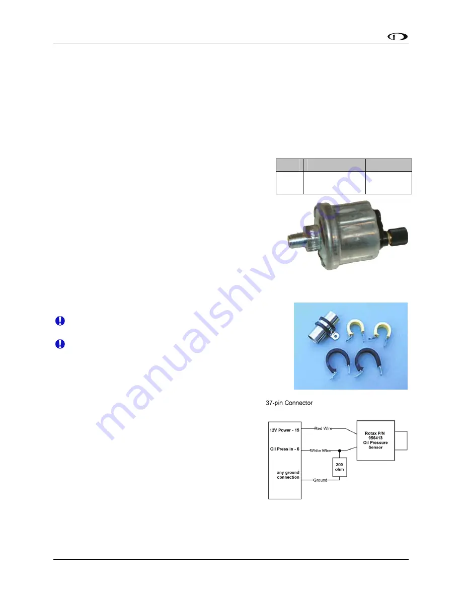
Pin 

Color 

Function

6 White/yellow 

Oil 

pressure 

3-6 


FlightDEK-D180 Installation Guide 

Use an Adel clamp similar to the 
above to secure the pressure sensor

Crimp a standard #8 ring terminal onto the white/yellow wire 
from pin 6. Unscrew the stud cap from the threaded stud. 
Place the ring terminal on the stud and secure the cap down 
sandwiching the ring terminal. 

1/8-27 NPT 

0-150 PSI 


Due to vibration issues, never connect the sensor 
directly to the engine.  


If you use Teflon tape or other seal, ensure the sensor 
casing still maintains a good connection to ground.  

JABIRU AND ROTAX OIL PRESSURE 

If you are installing on a Jabiru or Rotax engine, your engine 
comes with a pre-installed oil pressure sensor.  
Prior to mid-2008, Rotax provided an oil pressure 
sensor with 2 tabs for electrical connection. In mid-
2008, Rotax switched to a new type of oil pressure 
sensor (Rotax P/N 956413) with an integrated 2-wire 
cable. Connect this newer sensor according to the 
wiring diagram at right. Connect the red wire of the 
new sensor to EMS DB37 Pin 15 (12V). Connect the 
white wire of the new sensor to EMS DB37 Pin 6. 
Then, connect one end of a 200

 resistor to pin 6, 

and the other end to ground. The Jabiru and both types of Rotax oil pressure sensors are 
compatible with the FlightDEK-D180. Select the correct sensor type as described in the Oil 
Pressure Configuration section on page 6-9. 

Summary of Contents for FlightDEK-D180

Page 1: ...80 Installation Guide This product is not approved for installation in type certificated aircraft P N 100600 000 Revision H For use with firmware version 5 4 August 2010 Copyright 2003 2010 by Dynon A...

Page 2: ......

Page 3: ...ion of such changes Visit the Dynon Avionics website www dynonavionics com for current updates and supplemental information concerning the use and operation of this and other Dynon Avionics products L...

Page 4: ......

Page 5: ...er 3 4 Manifold Pressure Sensor 3 5 Oil Pressure Sensor 3 6 Oil Temperature Sensor 3 7 Fuel Pressure Sensor 3 7 Fuel Flow Sensor 3 9 Fuel Level Sensor 3 11 Ammeter Shunt 3 12 General Purpose Inputs 3...

Page 6: ...Brightness Configuration 7 5 Network Status 7 6 8 8 1 Autopilot Installation and Configuration Additional Information and Updates 8 1 DSAB Firmware Compatibility 8 2 Compass Calibration Critical For C...

Page 7: ...e Dynon distributors customize various areas of the FlightDEK D180 firmware to maintain a consistent pilot experience and minimize integration issues across a large number of installations Currently O...

Page 8: ...ctionality available only with the AP74 Autopilot Interface Module connected to your system Any text following this icon describes functionality that is possible when multiple Dynon Avionics products...

Page 9: ...t all wire you use also meets Mil Standard MIL W 22759 16 all wire supplied by Dynon Avionics with the exception of thermocouple wire which uses FEP insulation meets this specification When using any...

Page 10: ...180 has 3 pins on the 37 pin harness which may be used for connecting such sensors to ground More than one sensor s ground may be connected to any of these three grounds using a splice EMS DB37 Pin Co...

Page 11: ...to a desired length if your application requires If you need to extend the length of the thermocouple you must use the correct type J or K thermocouple wire to accomplish this It is acceptable to use...

Page 12: ...he EFIS 25 pin female harness If you purchased your harness from Dynon Avionics it is color coded according to the chart on the following page Unless noted otherwise all wires are 3 feet long on the D...

Page 13: ...9 Black bundled PC Serial Ground EFIS logging only Page 4 5 10 Orange bundled FlightDEK D180 Transmit PC Serial Receive RS 232 EFIS logging only Page 4 4 11 White Orange Red on some harnesses EDC D10...

Page 14: ...ram depicts the basic layout of the EFIS DB25 electrical connections and is for reference only Read the specific instructions for each connection prior to installation The colors shown refer to the Dy...

Page 15: ...pin female harness If you purchased your harness from Dynon Avionics pins 1 2 34 35 36 and 37 have wires inserted but are not used You may clip the wires or remove the pins as needed Refer to the fol...

Page 16: ...mit RS 232 EMS logging only Page 4 5 13 Black Ground Fuel Flow Page 3 9 14 Yellow Fuel flow input Page 3 9 15 Red Fuel flow power 12V Page 3 9 16 Black Ground Page 2 2 17 Black Ground Page 2 2 18 Whit...

Page 17: ...MS measures the Rotax supplied resistive CHTs through its GP inputs On the supplied harness each pair of wires is encased in brown insulation and labeled with corresponding cylinder number Inside the...

Page 18: ......

Page 19: ...some of the tools or equipment listed below may not apply to your installation Wire strippers 22 AWG wire if harness not purchased or extending harness beyond 6 feet D sub pin crimper Faston ring term...

Page 20: ...it for the hose clamps For best results mount all probes the same distance from each cylinder 1 Make sure the hole is placed to ensure that the probe does not interfere with the cowl or spark plug Als...

Page 21: ...ll and lock the collar to the adapter Now plug each thermocouple wire into its corresponding wire on the thermocouple harness Ensure that you match the wire color pairs on the harness to those on the...

Page 22: ...pickoff you must follow the instructions below The magneto P lead has high voltages which can very easily damage the FlightDEK D180 if not dealt with properly Use the two included 30k resistors color...

Page 23: ...d pins onto the ends of the wires ensuring that the long tabs that cradle the rubber seal wrap around the seal see picture at right for example For more details on preparing and crimping the Weather P...

Page 24: ...llation Guide Use an Adel clamp similar to the above to secure the pressure sensor Crimp a standard 8 ring terminal onto the white yellow wire from pin 6 Unscrew the stud cap from the threaded stud Pl...

Page 25: ...nsor nsor to a fixed location riate pe thread fitting you may need adapters r an Use the 0 30 PSI sensor he susceptible to voltage differences between the engine case and the negative terminal of the...

Page 26: ...8 ring terminal onto the brown wire from pin 8 Unscrew the stud cap from the threaded stud P ring terminal on the stud and secure the cap down sandwiching the ring terminal If the connection between t...

Page 27: ...vibration issues never connect the sensor directly to engine Do NOT use Teflon tape when screwing in any of the fittings FLOSCAN TRANSDUCER INSTALLATION The FloScan fuel flow transducer has female NPT...

Page 28: ...Transducer Installation 3 10 FlightDEK D180 Installation Guide...

Page 29: ...to pin 21 You may also connect third and fourth fuel level transducers to the general purpose inputs of your choice See the General Purpose Inputs section on page 3 13 for more information CAPACITIVE...

Page 30: ...path between the battery and starter Electrically the shunt should be placed so that it does not receive power when the master switch is off If it does receive power in this case it is possible for y...

Page 31: ...1 route its output to pin 24 the Amps High input on the 37 pin EMS connector General Purpose Inputs Dynon Avionics supports many sensors for which the FlightDEK D180 does not have dedicated inputs The...

Page 32: ...d Connect the other black white wire on the OAT probe to the desired GP input on the FlightDEK D180 main harness Again if using the EFIS 3 wire OAT simply route either the yellow or blue wire whicheve...

Page 33: ...n be used if 200 is not readily available Be sure to configure the firmware to recognize the fuel level sensor on the general purpose input s you ve chosen as described in the General Purpose Inputs s...

Page 34: ...the general purpose inputs as described in the General Purpose Inputs section on page 6 17 Additionally you will need to calibrate each flap trim sensor as described on page 6 6 3 16 FlightDEK D180 I...

Page 35: ...essories package Dynon P N 100446 000 included with the FlightDEK D180 You will be using one of these resistors for proper installation of your coolant temperature sensor EMS DB37 Pin EMS harness Colo...

Page 36: ...and to the General Purpose Temperature section on page 6 18 for configuration information Contacts Dynon Avionics does not sell contacts or switches Contacts are used for a variety of purposes such a...

Page 37: ...ire which may be used to connect the desired thermocouple to the FlightDEK D180 Ensure you order the correct wire type for the thermocouple you intend to use Crimp a female D sub pin on the end of eac...

Page 38: ......

Page 39: ...ut the space surrounding your location to get a r idea of the suitability of your chosen location If the needle deviates significantly from magnetic north in any given area that locatio would not be i...

Page 40: ...communication between the FlightDEK D180 and the EDC D10A remote compass module The Dynon supplied harness colors are listed as well EFIS DB25 pin EDC DB9 pin Function Wire color 11 5 EDC Data B White...

Page 41: ...f power Connect to a switched power source Will not be adversely affected by engine cranking 2 Keep Alive Power Yellow A very low current power input which is only used if both Master and External Bac...

Page 42: ...a version 5 0 of FlightDEK D180 firmware added internal data logging and retrieval via the Dynon Product Support Program The EMS Serial port DB37 is used for Streaming real time EMS engine data to an...

Page 43: ...duct Support Program s Detect Firmware Version function Download the latest version of the Support Program from the Dynon Web Site at downloads dynonavionics com EMS SERIAL HARNESS On the EMS 37 pin w...

Page 44: ...the GX50 and GX60 and Bendix King Skymap IIIc From the EFIS menu enter SETUP HSI EFIS_SERIAL from the EMS menu enter SETUP GLOBAL EMS SERIAL In that menu select the INPUT to be AVIATION and the BAUD R...

Page 45: ...f the EFIS that you have chosen to be the Bus Master This is the same Serial Rx line that is used for firmware updates You will need a way to disconnect this when you plug your EFIS into a PC for firm...

Page 46: ...re updates Do not connect any serial devices to the secondary EFIS device It will only display data from the serial devices connected to the master FlightDEK D180 Altitude Encoder Wiring 4 8 FlightDEK...

Page 47: ...Serial to Gray Code Converter as described in the Encoder Serial to Gray Code Converter Installation section on page 9 31 in the Appendix SERIAL ALTITUDE FORMATS There are four formats used by serial...

Page 48: ...of the external EMS warning by using the test function in the GLOBAL menu Enter the EMS menu by pressing any button beneath an EMS main page Press MORE SETUP GLOBAL Press DOWN to select ALARM CONFIG...

Page 49: ...r until the volume in the intercom or audio panel is at an acceptable level Verify that this volume is acceptable for EMS alarms which have a different tone Enter the EMS menu by pressing any button b...

Page 50: ...es the need to splice two wires together Wherever possible ensure that the two DSAB wires DSAB A and B are run as a twisted pair This minimizes the system s susceptibility to electrical noise Refer to...

Page 51: ...g it and have no significant roll angle in the panel The firmware supports an adjustment for panel tilt but not for mounting errors in yaw or roll Correct attitude performance depends on mounting the...

Page 52: ...ources must be available We recommend the FlightDEK D180 be connected to pitot and static systems in all installations To install simply connect your static and pitot sources to the FlightDEK D180 T i...

Page 53: ...Additionally this feature should not be used to zero out pitch when the aircraft is at an attitude other than level Do not think of this adjustment as you would the parallax adjustment on a normal att...

Page 54: ...he resulting data into your Dynon EFIS 3 Follow the instructions listed on the web page especially clicking the Compute Magnetic Field Values button at the bottom of the linked page the values require...

Page 55: ...up for at least 15 minutes before performing the calibration 2 Align the aircraft pointing magnetic North as closely as possible 3 On the FlightDEK D180 enter the menu system by pressing any button b...

Page 56: ...ssing MORE SETUP MORE MORE MAGADJ Increment or decrement the value of the heading offset until the FlightDEK D180 heading corresponds to the direction in which your plane is pointed Troubleshooting Du...

Page 57: ...nd Configuration FlightDEK D180 Installation Guide 5 5 3 Press BACK to return to the previous menu You will not be able to see some of the colors until the aircraft has achieved airspeeds in the range...

Page 58: ......

Page 59: ...enu the white area as shown at right When in a submenu press UP and DOWN to scroll through the available options If you have selected a value that can be toggled between a small number of values like...

Page 60: ...on has returned to normal values again AOA appears only on EMS Contact 1 and EMS Contact 2 When EMS Contact 1 or EMS Contact 2 is activated the AOA alarm in the EFIS section of the instrument is trigg...

Page 61: ...e instrument he or she may easily change units to whatever they desir without affecting calibration or configu Refer to the FlightDEK D180 Pilot s User Gu for more detailed information about the PILOT...

Page 62: ...connected EFIS based product or GPS the FlightDEK D180 will calculate percent power and lean of peak rich of peak status displaying both next to the Manifold Pressure gauge For percent power status t...

Page 63: ...er adding more engine types to our percent power calculations If your engine is not currently supported and you would like to see it considered for possible inclusion please send your engine s power c...

Page 64: ...l value distinct from the full value which you can reset the fuel computer to Finally the ADD THRESHOLD menu allows you to configure the fuel computer to automatically detect the addition of fuel when...

Page 65: ...just shows FLAPS followed by the GP input that each is configured as or NONE if no GP input is configured for a given axis Ensure that this list corresponds to the physical connections made during th...

Page 66: ...elds If you are using a p lead connection the PULS REV value will typically be set to or of the number of cylinders in the engine If you find that the onscreen tachometer reads double or half what you...

Page 67: ...able Sensor Type Oil Pressure Sensor 1 Dynon P N 100411 002 or Rotax 912 pre installed prior to mid 2008 2 GRT HPS 01 3 Jabiru pre installed 4 Rotax P N 956413 mid 2008 and later Sensor Type Oil Temp...

Page 68: ...ombined view If you have set the EGT CHT displays to be split on 2 3 EMS pages swapping to a 1 3 EMS will cause the EGT SCALE SECTIONS value to take precedence over the CHT SCALE SECTIONS SPAN ALARMS...

Page 69: ...displays 2 and 4 cylinders only you can set the SCALE SECTIONS for EGT and CHT independent of each other For COMBD displays EGT and CHT SCALE SECTIONS are tied together as the two sets of measurement...

Page 70: ...DOWN to select DETECT below SHOCK COOLING Then press SEL to toggle the DETECT setting to ON Like other alarms you can cycle ALARM through SELF CLEAR LATCHING and OFF See Alarm and Color Threshold Conf...

Page 71: ...or Type Fuel Pressure Sensor 1 Dynon P N 100411 000 carbureted 2 Dynon P N 100411 001 injected 3 GRT LPS 02 remove the external pull up resistor Fuel Pressure If a fuel pressure transducer has been in...

Page 72: ...onfiguration menu If you have lost your tag a starting K value of 30000 will be close enough to begin using the function If you have the EI FT 60 Red Cube Dynon P N 100403 003 enter a starting K VALUE...

Page 73: ...only positive currents 0A TO 60A used for Locations B and C This will depend on your installation as mentioned in the Ammeter Shunt installation section on page 3 12 Select the alarm mode and the anal...

Page 74: ...t the FUNCT for all unused GP inputs to UNUSED ROTAX CHT Select GP INPUT 1 and press SEL to change the FUNCT parameter to ROTAX CHT L Back out and select GP INPUT 2 and press SEL to change the FUNCT p...

Page 75: ...bar thresholds as described in the Alarm and Color Threshold Configuration section on page 6 2 Set the SENSOR TYPE to the correct number using the sensor type table If you have installed a Dynon Avio...

Page 76: ...OR EMS CONTACT 1 or CONTACT 2 Select the alarm mode as described in the Alarm and Color Threshold Configuration section on page 6 2 Contacts can only be configured as an INFO ITEM Configure the contac...

Page 77: ...ms press DOWN to select the LABEL 1 field The first character of the 4 character name is highlighted Press INC or DEC to cycle through the numbers and letters for the first character When you have sel...

Page 78: ......

Page 79: ...EFIS D100 EMS D10 EMS D120 FlightDEK D180 HS34 SV32 42 52 AP74 Bus Master X X EFIS X X EMS X X OAT X X X Compass X X HS34 X Autopilot X X AP Control Panel X AP Roll Pitch Servo X The table at right l...

Page 80: ...first diagram depicts a system without an HS34 connected demonstrating where NAV and GPS devices should be connected The second diagram depicts a system with an HS34 connected demonstrating that all...

Page 81: ...DSAB Configuration FlightDEK D180 Installation Guide 7 3...

Page 82: ...to wait while the instrument detects all other devices connected via DSAB While doing this it assigns both the Bus Master and EFIS roles to itself During network detection the Bus Master attempts to...

Page 83: ...Press FINISH to end the configuration Press UP and SEL to view the status of all connected DSAB devices Press UP or DOWN to scroll through all the devices Cross check the displayed devices against wha...

Page 84: ...evice is communicating normally on DSAB STANDALONE During configuration as Bus Master no other DSAB devices were found UPGRADE REQ Device has a different firmware version than the Bus Master and thus...

Page 85: ...hnical Support for details Dynon also offers the AP74 Autopilot Interface Module which provides dedicated AP control via panel mounted buttons and a knob Dynon offers mounting kits for specific airfra...

Page 86: ...running the same firmware version currently version 5 4 This applies to the servos and AP74 as well Because the servos and AP74 are updated via the DSAB Bus Master EFIS the EFIS that you wish to contr...

Page 87: ...Autopilot System Electrical Installation The diagram below provides an overview of the autopilot electrical system The following sections describe the electrical installation of each subsystem in deta...

Page 88: ...ightDEK D180 White Blue Reserved for compatibility with Dynon Next Generation products DO NOT CUT During servo installation Dynon recommends that this be routed to the cockpit panel include sufficient...

Page 89: ...stalling the AP74 we recommend building enough slack wiring into the D25 connector to allow the AP74 to be removed from its tray with the connector attached Use the D sub pins connector kit included w...

Page 90: ...njury or death If there are any questions on the part of the installer it is mandatory to resolve these questions prior to flight When installing the servo you must first determine a mount location fo...

Page 91: ...r the arm and attached linkage to move through a complete range of motion without interference CAUTION In normal operation Dynon s servos can reach temperatures that can be very uncomfortable to and p...

Page 92: ...lowing dimensions in inches for reference when planning and implementing your installation 8 8 FlightDEK D180 Installation Guide Long arm variants not needed in most installations have linkage mount h...

Page 93: ...48lb B 58lb C 72lb Long Arm Max Linear Travel A 3 4 B 3 0 C 2 6 Max Force 100 Torque SV32L A 18lb B 20lb C 24lb SV42L A 27lb B 31lb C 36lb SV52L A 36lb B 41lb C 48lb In most instances we recommend th...

Page 94: ...existing mechanicals of the aircraft Some systems will use a hole drilled into the bell crank as the point where the servo push rod rod end combination interfaces with the controls Others will use an...

Page 95: ...nsions in inches found on the diagram to plan for the space required by the instrument The front bezels of the vertically oriented AP74 100756 000 and are the same height as Dynon s D100 series produc...

Page 96: ...to positively secure the bracket to the panel if desired While not required for secure mounting the mounting screw clamps the panel between the bezel and bracket securing the bracket to the panel can...

Page 97: ...he mounting flange it will also be drawn forward into the back of the panel when tightened Tighten until the flange and bracket are securely fastened to the panel Firmware Upgrades Required For AP Fun...

Page 98: ...ng Pilots should consult the FlightDEK D180 Pilot s User Guide for a comprehensive description of AP operation Note Before proceeding verify that power is ON for all EFIS EMS HS34 AP74 and servo s Not...

Page 99: ...when these devices were purchased separately from upgrade via the Bus Master EFIS even if the EFIS After the above verification press BACK EXIT STEP 2 SERVO CALIBRATION AND SERVO TEST The Servo Calibr...

Page 100: ...s canceled the AP status display at the lower left of the EFIS screen shows TST as the status for the installed servo s After successful calibration the screen displays PLEASE CENTER ALL CONTROL SURFA...

Page 101: ...he HDG bug synchronizes to the current heading and the roll servo engages Ensure that the controls do not deviate far from center If you have an AP74 installed and configured you can accomplish this s...

Page 102: ...autopilot to use in a turn see below Step 3d Set Roll Servo Bank Limit The BANK LIMIT parameter specifies a maximum bank angle which the AP will not exceed during turns Setting an appropriate Bank Li...

Page 103: ...down or pitch up remember you are only overriding the pitch servo so you should feel no resistance in the roll axis Ensure that you are comfortable with the amount of force it takes to override the se...

Page 104: ...be set to the specifications of your aircraft in the EFIS SETUP IASCLR menu The AP cannot be engaged at airspeeds below Airspeed Minimum with the exception of 0 knots allowing for ground testing When...

Page 105: ...ows you to engage the Autopilot by holding the Disengage CWS Button for more than 2 seconds This allows for a convenient alternative to engaging the Autopilot via the menus and or AP74 AP button Defau...

Page 106: ...ing Mode When the Control Wheel Steering ENABLED parameter is set to Y the MODE parameter selects between two different ways of reengaging the Autopilot after the AP Disengage CWS Button is released L...

Page 107: ...setting EMS AUDIO ALERTS RPM HIGH MANIFOLD PRESSURE HIGH OIL PRESSURE HIGH LOW OIL TEMPERATURE HIGH LOW EGT 1 6 HIGH LOW EGT SPAN CHT 1 6 HIGH LOW CHT SPAN CHT 1 6 SHOCK FUEL LEVEL 1 4 LOW FUEL PRESSU...

Page 108: ...eness Before commencing these configuration steps ensure that you ways have adequate altitude clear weather no traffic no obstructions in the flight path great visibility etc If possible bring someone...

Page 109: ...itude stays constant Step 8c Engage the AP in HDG mode On the EFIS perform the following EFIS AP HDGOFF The EFIS synchronizes the HDG bug to the current heading the Autopilot engages with the heading...

Page 110: ...ent heading Change the HDG bug to 90 degrees to the left or right of current heading via any of these methods On the EFIS enter the EFIS AP BUGS HDG menu and press INC or DEC to set desired heading On...

Page 111: ...articular Min Max and Vertical Speed Max u r during flight push DOWN to select fy it rim de owing STEP 9 PITCH SERVO FLIGHT TUNING This set of procedures tunes the settings in the AP PITCH SERVO menu...

Page 112: ...e target altitude The AP should keep the inverted trian of the altitude bug closely aligned with the triangle of the numerical magnetic altitude indicator as shown at right P gle If excessive wanderin...

Page 113: ...REASE POWER message is displayed If necessary adjust the AIRSP MIN AIRSP MAX and VSPD MAX parameters as described above At this point all the parameters in the AP PITCH SERVO menu are properly tuned S...

Page 114: ...ding bug or barometer is the first action to be adjusted by the knob If REQUIRE PUSH is set to YES The first push of the VALUE knob activates the FIRST ACTION mode ALT HDG or BARO and displays a pop u...

Page 115: ...heading and altitude at the time of AP engagement this will result in the AP immediately commanding a turn and a climb or descent at time of engage When using this mode we recommend that you verify t...

Page 116: ......

Page 117: ...t required AP SERVO INSTALLATION At least once per year inspect the installation of the AP servo s for excessive wear Ensure that all hardware and fasteners are tightly secured ALTIMETER CHECK The fol...

Page 118: ...battery replacement instructions Please dispose of non functional backup batteries in a responsible manner Backup batteries are lithium ion and similar in construction to cordless tool batteries They...

Page 119: ...this alert The grey black horizon indication and onscreen message will remain until the unit has resumed normal operation In the case of rotation rate greater than 150 degrees second the unit enters...

Page 120: ...verified that the wiring to the EDC D10A is correct Please see the FlightDEK D180 Installation Guide for more information on verifying the installation of the EDC D10A This error also can appear if y...

Page 121: ...te your FlightDEK D180 s zero pressure value With your plane in as windless an environment as possible e g a hangar cover both the pitot and static ports with a sock or cloth to minimize airflow witho...

Page 122: ...oubleshooting with a Dynon representative the issue cannot be resolved we will provide you with an RMA number to use when shipping the FlightDEK D180 to us If your unit is still under warranty the rep...

Page 123: ...non Avionics EDC D10A remote compass module 2 machined D sub pins D sub pin crimp tool Loctite INSTALLATION Mount Location It is important that the OAT probe be mounted somewhere on the skin of the ai...

Page 124: ...K D180 to recognize the OAT The FlightDEK D180 supports two different types of OATs as well as a manual input of the outside temperature To set this up enter the menu system by pressing any button ben...

Page 125: ...ove OAT value is consistently high low You need to adjust the displayed OAT value to correct for sensor inaccuracies Follow the instructions in the Calibration and Adjustment section above OAT display...

Page 126: ...may also find it helpful to own a pin insertion extraction tool part numbers DSE 1 and SAT 023 respectively Power Requirements 22 AWG wire is normally sufficient for the power supply and ground lines...

Page 127: ...up UP 5 GP Output 1 not currently supported 5 GS when FLAG shown 6 GP Output 2 not currently supported 6 DME Analog IN 0 8V 40mv NM 7 GP 1 in same as EMS GP in 7 Resolver G 8 GP 2 in S GP in same as...

Page 128: ...de in every HS34 intercom system Once properly configured on your DSAB network this connection sch allows you to use your HS34 s VALUE knob with the DSAB Bus Master Refer to the Dynon Smart Avionics B...

Page 129: ...red over serial serial preferred over analog ARINC data streams contain more information vertical GPS guidance GPS steering etc than serial streams and allow more control of your external device Likew...

Page 130: ...n radios and GPSs and the preferred connection schemes between them and the HS34 Make note of whether the connections are to the male or female connector on the back of the HS34 When constructing your...

Page 131: ...Appendix FlightDEK D180 Installation Guide 9 15...

Page 132: ...Appendix 9 16 FlightDEK D180 Installation Guide...

Page 133: ...e diagram to plan for the space required by the instrument The front bezel of the vertically oriented HS34 100755 000 is the same height as Dynon s D100 series products and can be mounted close to or...

Page 134: ...ounting tab to your panel in whatever way you desire Riveting it to the panel is ideal but drilling holes for mounting screws and nuts also works Upon securing the mounting tab to the back of your pan...

Page 135: ...is device ata push DOWN to select the cted to the SERIAL 1 RX and TX pins ending on the output format configured ected to the serial pins is a Garmin L30 CMD ed by your SL30 or GPS Many ud rate ensure...

Page 136: ...N parameters As a general rule of thumb if the schematic for your receiver shows the 3 discrete outputs connected to lights whose other side is connecte power set PULL UP to Y and ACTIVE WHEN to LOW L...

Page 137: ...the HS34 to report tones or voice alerts during EMS alarm conditions This setting has no effect on the direct audio output of the EMS EFIS EXT TONE EXT VOICE Sets whether you want the HS34 to report t...

Page 138: ...UIRE PUSH is set to YES The first push of the VALUE and n the table above and is configured from HSI SET h before rotating the knob IR r B urrent mode and value Rotating th ST ACTION mode ALT o knob w...

Page 139: ...nnected to the HS34 is displayed Only if the HS34 fails the NAV and or GPS data connected to the EFIS and or EMS is temporarily displayed There is no indication provided that the data being displayed...

Page 140: ...s not operate like a normal heated pitot it will still get fairly hot in normal ambient temperatures When turned on it will regulate its internal temperature to about 70 C to 80 C To ensure that the h...

Page 141: ...the instructions in this s rsion of the probe you may skip to the AOA Pitot P ollow these instructions explicitly as improper th end the re the heater controller via the 4 mounting holes Route the wi...

Page 142: ...probe and heater controller This diagram basic layout of the electrical connections between the should be used in conjunction with detailed prior to instructions on the following pages Read the speci...

Page 143: ...carry any significant current you may extend them with 26 AWG or larger for any run length Controller Power wiring Three wires colored red black and white exit the controller for connection to your el...

Page 144: ...e If you use an LED as the indicator you must choose a resistor that delivers the appro ater is turn t functionin nel whose nal is and functioning properly the wh ff When there is no power to the requ...

Page 145: ...Appendix these lines you may drill all the way through the outer metal without affecting the probe s waterproofing DIMENSIONS Standard mount FlightDEK D180 Installation Guide 9 29...

Page 146: ...ing these holes does not guarantee a pneumatic seal although one is sometimes present The leak that may exist does not affect the performance of the probe You will however need to take it into account...

Page 147: ...OABAR menu This calibration should result lowest angle of attack stall occurring just above the red yellow boundary If this is not the ca please repeat the AOA user calibration including flight config...

Page 148: ...ase but m necessary to complete the installation Wire cutters Connector crimp tool Crimp pins 25 pin EFIS harness to mate with FlightDEK D180 may have been purchased with your FlightDEK D180 Connector...

Page 149: ...value is set to 29 92 in ing connections to the FlightDEK D180 check to ensure that the wire length between will facilitate an installation that is both cleaner r Converter installation are pins 13 an...

Page 150: ...n M older m ial Encoder Transmit hite may be lack on some G ay be Red on odels Ser 21 White Black Serial Encoder Ground STEP 3 FLIGHTDEK D180 ENCODER FORMAT For proper communication the EFIS Altitude...

Page 151: ...insulation Refer to the 37 Pin Female EMS H E fer to the Fuel Level configuration section on page 6 13 for fuel level sender type configuration and page 6 5 for fuel level sender calibration apacitan...

Page 152: ...rcraf es t be aware of i and how lan e ing a on ed g 3 6 oz 0 102 kg 3 2 oz 0 08 kg g 6 oz 0 16 kg 4 oz 0 11 kg il temperature sender 2 oz 0 06 kg Flush mount bracket 2 oz 0 06 kg EMS 37 pin wiring ha...

Page 153: ...Appendix FlightDEK D180 Installation Guide 9 37 OAT sender 3 oz 0 09 kg 0 11 kg g Fuel flow sender 4 oz Carburetor temperature sender 2 oz 0 06 kg Ammeter shunt 5 oz 0 14 k...

Page 154: ...Sensor Inputs 6 EGT Type K Thermocouple 6 CHT Type J Thermocouple 2 Fuel Level Resistive or Capacitance with 5 volt output 2 RPM P lead or pickup 2 Contacts 1 Manifold Pressure voltage 1 Oil Temperatu...

Reviews: