


4
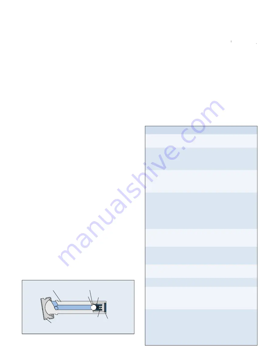
PISTON SHOE
INLET SEAT
INLET CHECKBALL
INLET SPRING
INLET BALL STOP
PISTON
RETAINER
FIGURE 3: Typical piston assembly showing piston shoe and inlet
checkball components inside piston.
checkball components inside piston.
Part Inspection, Evaluation and Reconditioning
Part
Inspection Procedure
Barrel
Check piston bores for galling or
excessive wear.
Outlet Seats
and Checkballs
Using microscope, check for pitting
and excessive wear. Always replace
seats and checkballs as a matching
pair.
Outlet Springs and
Control Springs of
Variable Models
Check for set, worn (end coils and coil
ID) or bent or broken springs. Replace
all springs as standard hydraulic ser-
vice practice.
Piston
Assemblies
(Refer to
Figure 3)
Check for galling on outer diameter of
each piston, damage or wear to piston
shoes, inlet seat pitting or excessive
coining/recession, excessive wear to
inlet ball stop. Confirm inlet checkball
is seating properly (See procedure on
page 5).
Piston Return
Springs and
Spring Retainers
If present, check for excessively worn
or bent springs and worn spring
retainers.
Bearings,
Thrust Plates and
Wobble Plate
Replace if any pitting is present or if
roller/race surfaces have excessive
wear.
O-rings
and Seals
Replace all seals during reassembly,
as standard hydraulic service practice.
Drive Shaft
Check for excessive or abnormal wear.
Face Surface
of Barrel
and Cover
Use a fine-grit oil stone (i.e., India
Medium) to remove any nicks and
ensure flatness on the faces. Replace
if any nicks are near sealing surface.
Thrust Plate
Surface
(Some Models)
Lap the surface of the plate that
contacts the piston shoes. Use several
figure-8 motions on 600 grit wet/dry
paper on a flat plate or stone until
surface is uniform. Replace the
bearing if deep nicks or abrasion
are evident.
2. Absolute cleanliness is necessary while working to pre-
vent contamination and potential pump damage.
3. To aid proper reassembly, note the relative position of the
housing, barrel and cover (some models). Apply a paint
stripe or center punch marks on the external service
across the seams.
4. Be prepared with new seals and o-rings, which should be
installed during reassembly as standard hydraulic service
practice.
IMPORTANT: If a system component fails resulting in fluid
contamination, it is important to drain and clean the reservoir,
all lines, filter screens and all components. Refill the system
with new fluid. This must be done to prevent immediate failure
of new pump when replacing a failed pump.
Disassembly Notes
1. Handle parts with care to prevent nicks and scratches on
critical machined surfaces. As parts are removed and set
aside for inspection, cover them with a clean cloth for
protection.
2. Keep similar, non-identical parts (springs, checkballs,
bearing plates) separated and identified to avoid confu-
sion during reassembly.
3. Be careful when separating the barrel and housing, which
may spring apart in models with spring-loaded parts.
4. To avoid damage, the pistons need to be retained in the
barrel as it is separated from the housing. Tip the barrel
slightly to keep the piston assemblies in place.
5. In some pump models, removal of outlet seats or retain-
ers may be difficult without using a special tool. Contact
the sales department for more information.
If excessive wear requires replacement, it may be more
advantageous to replace the entire barrel.
6. Similarly, if a piston is stuck in the barrel, it is likely that
the piston bore was damaged. Replacement of the entire
barrel is recommended.
Reassembly Notes
1. Replacements for certain parts must be ordered as a kit.
Typically, these include the seals and o-rings, pistons,
outlet check valves, the shaft and bearings, and any
pump control components (i.e. pressure compensator
assembly). Refer to the specific Parts List, or contact the
sales department for kit numbers.
2. During reassembly, coat all parts in pump fluid or com-
patible grease.
3. Replace all seals and o-rings as standard hydraulic practice.
4. To assure correct assembly sequence and orientation,
refer to the marks applied to the external surfaces (See
“General Guidelines”, step 3).
5. When applying adhesive sealant (
Loctite
®
Threadlocker
®
®
,
Threadlocker
Threadlocker
or equivalent), apply enough sealant to coat one or two
center threads. Do not apply excessive sealant that can
seep beyond the thread area.
6. Refer to the specific Parts List for proper torque values
when installing parts.
7. To prevent damaging the seal when installing over the
shaft, the keyway or spline should be masked with thin
tape and coated with grease.
8. Before installing the pistons, check each one to confirm
that the inlet checkball is seating properly. See page 5.


