background image


AIR Control software

Dynaudio Professional AIR reference manual – 2014-09-28 


73

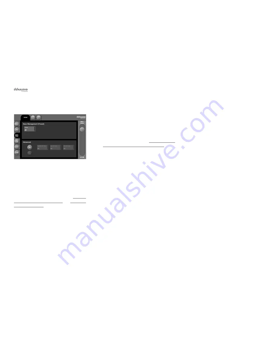
Bass management page

Fig. 42: AIR Control software – Global – Bass 
management page

Use the Bass management page in the Global section 
of the AIR Control software to recall Bass management 
presets and activate Advanced bass management fea-
tures.

To learn more about bass management, see “Configur-
ing bass management” on page 21 and “Bass man-
agement” on page 117.

Recalling Bass management presets


Click the Preset field in the Bass Management 
(Preset) section of the bass management page. 
This will assign Bass management preset selection 
to the large slider on the right of the window.


Drag the slider to select the desired bass manage-
ment preset.

For a description of the bass management presets, 
their parameters and values, see “Bass management 
modes and crossover frequencies” on page 21.

Advanced bass management

In bass management presets, the states of the three 
filters (Satellite, Sub 4 and Sub 2) are predefined. Using 
Advanced bass management, you can activate these 
filters individually for fine-grained control of demanding 
speaker setups.

To activate Advanced bass management, click the On 
button in the Advanced section of the Bass manage-
ment page. This will enable the remaining buttons in 
this section.


Click the field for the filter (Satellite HP, Sub 4th 
order or Sub 2nd order) that you want to configure. 
This will assign this filter to the large slider on the 
right of the window.


Set the desired crossover frequency for this filter or 
drag the slider down to set the filter to Off.


Click the LFE = Sub button to include the LFE 
channel in bass management.

Summary of Contents for AIR 15

Page 1: ...Dynaudio Professional AIR Reference manual 2014 09 28 ...

Page 2: ...p analog 35 5 3 setup digital 36 5 3 setup analog 37 6 1 setup analog 38 5 1 setup with Digital AES EBU card 40 Stereo setup with chains on left and right 41 7 1 setup analog or digital 42 5 1 setup digital 192 kHz 44 6 1 setup digital 192 kHz 45 Recalling and storing presets 46 Recalling presets 47 Storing presets 47 Parameter storage 47 Placing the monitors 48 Overview 49 General considerations ...

Page 3: ... size and typical listening distance 99 General specifications for AIR 6 AIR 15 AIR 20 AIR 25 AIR BASE 1 AIR BASE 2 AIR BASE 12 AIR Base 24 100 AIR Remote 101 General specifications for all products 102 Delay in system 103 Certificate of conformity 104 Appendix Acoustics 106 Introduction 107 Sabine s formula 108 Absorbers 109 Diffusors 110 Standing waves 111 Comb filtering 113 Rear wall cancellati...

Page 4: ... Important safety instructions Dynaudio Professional AIR reference manual 2014 09 28 1 Important safety instructions ...

Page 5: ... lightning storms or when unused for long periods of time 14 Refer all servicing to qualified service person nel Servicing is required when the apparatus has been damaged in any way such as pow er supply cord or plug is damaged liquid has been spilled or objects have fallen into the appa ratus the apparatus has been exposed to rain or moisture does not operate normally or has been dropped Warning ...

Page 6: ...no guarantee that interference will not occur in a par ticular installation If the equipment does cause harmful interference to radio or television reception which can be determined by turning the equipment off an on the user is encouraged to try to correct the interference by one or more of the following measures Reorient or relocate the receiving antenna Increase the separation between the equip...

Page 7: ... Before you begin Dynaudio Professional AIR reference manual 2014 09 28 4 Before you begin ...

Page 8: ...ging the equipment connected to the monitors Always turn off the speaker and other equipment when plugging or unplugging signals or switching equipment on or off Do not touch the drive units by hand Break in time The transducers of your Dynaudio Professional AIR monitor will achieve better sound quality after breaking in Especially after the first hours of use you may notice a significant advance ...

Page 9: ...h or you may miss important information This manual is available as a PDF download from the Dynaudio Professional website Of course you can print this manual but we encourage you to use the PDF version which has both internal and external hyperlinks For example clicking the logo in the upper left corner of each page will take you back to the table of contents To download the most current version o...

Page 10: ... The AIR concept Dynaudio Professional AIR reference manual 2014 09 28 7 The AIR concept ...

Page 11: ...nitors and are excellent for both stereo and surround setups in applications such as mu sic recording mixing post production film broadcast video editing etc Extreme precision The frequency response and timing of the woofer and tweeter signals of AIR monitors is controlled to a level of precision only practically obtainable with DSP Fur thermore the sensitivity of each individual loudspeaker drive...

Page 12: ...all connected mon itors in the entire system either using AIR control soft ware or from a Master monitor that acts as the System Controller monitor One and only one of the Master monitors must be set up as the System Controller This is done by set ting the TC LINK button on the rear panel to the Out position Air Slave units A Slave unit is able to receive and distribute audio and control data via ...

Page 13: ...ector Audio and control data are sent from the Master unit to the Slave units via the RJ45 Input connector The RJ45 Link connector can be used for data transmission to additional monitors Initializing the network When the setup is powered up for the first time the Master unit scans the setup in order to determine the number of monitors connected Each monitor is recog nized via a unique serial numb...

Page 14: ...vanced tools and features inside AIR monitors and subwoofers in cluding timing and SPL calibration and parametric EQs for each monitor AIR Control lets you define and store custom setups and presets with selective parameter locking and a special measurement mode provides EQ line signal out from selected monitors To download AIR Control software go to dynaudioprofessional com air series monitors ai...

Page 15: ...IR Control software see Preferences page on page 76 Activating Power Save mode manually In general you should activate Power Save mode in stead of powering your AIR system down using the main switches To activate Power Save mode manually press and hold the Exit button on the System controller To wake your AIR system from Power Save mode press any button on the System controller Your AIR system wil...

Page 16: ... Rear panel controls and connections Dynaudio Professional AIR reference manual 2014 09 28 13 Rear panel controls and connections ...

Page 17: ... Controller Slave switch Out position The monitor operates as a System Controller There can be only one System Control ler in a setup In position The monitor operates as either a regu lar Master or a Slave unit 2 RJ45 Link connections for downstream Slave units 3 Option slot with analog I O card installed optional 4 AES EBU digital Input 5 Word Clock BNC sync input 6 Power input 100 to 240 V 7 Pow...

Page 18: ...r downstream Slave units 2 Power input 100 to 240 V 3 Power On Off switch Digital I O card optional Fig 5 Digital I O card optional With this card installed in the option slot of the Master unit a 5 1 Digital 6 Master setup becomes an option Three AES EBU connections 6 channels can then be fed to one Master monitor and distributed downstream For more information see Setups ...

Page 19: ... Operating your AIR monitors Dynaudio Professional AIR reference manual 2014 09 28 16 Operating your AIR monitors ...

Page 20: ...verload Indication LED When this LED flashes the monitor s built in amp is driven beyond maximum performance A continuous overload will activate the amp protection circuit and the monitor will be shut down The monitor can be reacti vated after a short period of cooling down This situation will NOT damage the monitor in any way Basic navigation operation Use the two arrow keys to select a value for...

Page 21: ... Select task No task L Front R Front Center C SUB L Sur R Sur C Sur L SUB R SUB L Chain R Chain L Inner Custom 1 4 External clock BNC Sync xxx Select clock BNC Input Off BNC Input On Input Sensitivity A Input Gain Sensitivity A Input 9 dBu 15 dBu 21 dBu 27 dBu Calibrate monitor Select AIR Master xxxx For AIR monitors Pink Noise Off On Calib 0 0 dB Rel Lev 5 0 dB Position Neutral Wall Corner Consol...

Page 22: ... AIR Menu structure and parameters Dynaudio Professional AIR reference manual 2014 09 28 19 AIR Menu structure and parameters ...

Page 23: ...t ups on page 29 Home screen Fig 7 AIR monitor home screen showing the sample rate the monitor s task and the volume The home screen of your AIR Master unit will show the role position of the monitor once it has been set up and the set volume for this unit A in the upper right corner indicates that this spe cific Master Unit has been set up to act as the System Controller see System Controller Mas...

Page 24: ...sing the UP and DOWN keys After setting the desired mode press the EXIT key to close the menu Bass management modes and crossover frequencies Displayed name Bass management mode name Satellite filter Sub 4th order Sub 2nd order LFE Sub Off No bass management only the LFE channel is distributed to the sub X Over 50 Hz X Over 50 Hz 50 Hz 50 Hz 50 Hz No X Over 80 Hz X Over 80 Hz 80 Hz 80 Hz 80 Hz No ...

Page 25: ...n to the home screen Setup name Remarks Empty No selection Custom For custom configurations Stereo analog Two monitor stereo setup with analog inputs selected Stereo Digital Two monitor stereo setup with digital inputs selected 5 1 Analog 5 1 setup with analog inputs selected 5 1 Digital 5 1 setup with digital inputs selected 6 1 Analog 5 1 Setup Center surround on a separate channel gives the 6 1...

Page 26: ...s the DOWN key until Set monitor tasks is displayed Press the ENTER key Press the UP and DOWN keys to select a monitor Each monitor is identified by its serial number which is shown on a label with a barcode on the back Press the ENTER key Press the UP and DOWN keys to select a monitor task Press the ENTER key to confirm your selection Press the EXIT key repeatedly to return to the home screen Dis...

Page 27: ...ENTER key Press the DOWN key until External clock is displayed Press the ENTER key Select clock is displayed Press the UP and DOWN keys to select the de sired mode Press the ENTER key to confirm your selection Press the EXIT key repeatedly to return to the home screen Display clock mode name Remarks BNC Sync On The monitor attempts to lock on the Word Clock BNC BNC Sync Off The monitor will attemp...

Page 28: ...N key until Setup menu is dis played Press the ENTER key Press the DOWN key until Sensitivity is dis played Press the ENTER key Sensitivity is displayed Press the UP and DOWN keys to select the de sired sensitivity Press the ENTER key to confirm your selection Press the EXIT key repeatedly to return to the home screen Analog input sensitivity settings 9 dBu 15 dBu 21 dBu 27 dBu Fig 10 Analog input...

Page 29: ...bra tion parameter Press the ENTER key to activate the selected parameter for editing Press the UP and DOWN keys to set the selected parameter to the desired value Press the ENTER key to confirm your selection Press the EXIT key to move up one level in the hierarchy and select another parameter for editing or Press the EXIT key repeatedly to return to the home screen Notes regarding the LFE channe...

Page 30: ... 6 dB Level calibration of the selected monitor Rel Lev Relative Level 40 dB to 0 dB Preset volume for the selected monitor relative to the calibrated and global volume LFE Low Pass On Off Brick wall Limiter on the LFE channel attenuating frequencies above 120 Hz LFE Gain 6 to 8 dB With this parameter you can boost the acoustic gain of the LFE channel Polarity 0 180º If the Subwoofer is correctly ...

Page 31: ...nected monitors will be reset to default settings Clearing the setup for the entire network From the home screen press the ENTER key Press the DOWN key until Setup menu is dis played Press the ENTER key Press the DOWN key until Clear setup for entire network is displayed Press the ENTER key Accept to clear network setup is displayed Press the ENTER key to clear the setup or press the EXIT key to d...

Page 32: ... AIR setups Dynaudio Professional AIR reference manual 2014 09 28 29 AIR setups ...

Page 33: ... as the System Controller To set a Master monitor as System Controller the TC LINK button on the rear panel of this monitor must be set to the Out position The TC LINK button on all other Master monitors must be set to the In position Reading the setup illustrations The AIR Remote shown in most setups is an op tional hardware remote control For more informa tion see AIR Remote on page 63 Audio sig...

Page 34: ...and using this setup Audio signals are represented by solid lines TC link signals are represented by dashed lines The left monitor is set as the System Controller by setting the TC Link button on the rear panel to the out position The left monitor receives both the left and right input signals The right monitor receives audio via the TC LINK RJ 45 connection The AIR Remote or a computer running th...

Page 35: ... dashed lines The left monitor is set as the System Controller by setting the TC Link button on the rear panel to the out position The left monitor receives both the left and right input signals The right monitor and the subwoofer receive audio via the TC LINK RJ 45 connection from the left monitor With no bass management no signal is sent to the subwoofer With bass management activated low freque...

Page 36: ...setting the TC Link button on the rear panel to the out position The left monitor receives both the left and right input signals The right monitor and the subwoofers receive audio via the TC LINK RJ 45 connection from the left monitor With no bass management no signal is sent to the subwoofers With bass management activated low frequency information is extracted from the left and right channels be...

Page 37: ...ives both the left and right input signals The right monitor receives audio via the TC LINK RJ 45 connection from the left monitor The left surround monitor LS receives both the left and right surround channel signals The right surround monitor receives audio via the TC LINK RJ 45 connection from the left surround monitor The center monitor C receives both center and LFE channels The LFE monitor r...

Page 38: ...nput signals The right monitor receives audio via the TC LINK RJ 45 connection from the left monitor The left surround monitor LS receives both the left and right surround channel signals The right surround monitor receives audio via the TC LINK RJ 45 connection from the left surround monitor The center monitor C receives both center and LFE channels The LFE monitor receives audio via the RJ 45 co...

Page 39: ...rround input signals The left surround monitor is fed via the TC LINK RJ 45 connection from the left monitor The right surround monitor is fed via the TC LINK RJ 45 connection from the right monitor The center monitor C receives both center and LFE channels The LFE monitor receives audio via the RJ 45 connection from the center monitor With bass management off the left and right sub woofers will r...

Page 40: ...ital 5 3 setup re garding bass management but make analog connec tions as explained in this section The left input of the left monitor receives the left signal The right input of the left monitor receives the left surround signal The left input of the center monitor receives the center signal The right input of the center monitor receives the LFE signal The left input of the right monitor receives...

Page 41: ...center and LFE channels The LFE monitor receives audio via the RJ 45 connection from the center monitor The left surround monitor LS receives both the left and right surround channel signals The right surround monitor receives audio via the TC LINK RJ 45 connection from the left surround monitor The center surround monitor receives only the center surround signal Center Chain Starting with AIR sof...

Page 42: ...o the right input on the left mon itor Center channel to the left input on the center monitor LFE channel to the right input on the center monitor Left surround channel to the left input on the left surround monitor Right surround channel to the right input on the left surround monitor ...

Page 43: ...position The Center monitor receives all six channels on its three AES EBU connections The monitor s Digital IN connection receives the Center and LFE signals The digital input No 2 on the I O card receives the left signal and the right signal The digital input No 3 on the I O card receives the left surround signal and the right surround signal The right left left surround and right surround monit...

Page 44: ...ternate be tween a set of main and nearfield monitors The left monitor is set as the System Controller by setting the TC Link button on the rear panel to the out position The left monitor receives both the left and right input signals The right monitor receives audio via the TC LINK RJ 45 connection from the left monitor The AIR Remote or a computer running the AIR Control software both optional c...

Page 45: ...The left monitor receives both the left and right input signals The right monitor is fed via the TC LINK RJ 45 connection from left to right The center monitor receives both the Center and LFE signals The LFE monitor is fed via the TC LINK RJ 45 connection from Center to LFE The left surround monitor receives both the left sur round and right surround signals The right surround monitor is fed via ...

Page 46: ...eft input of the center monitor receives the center signal The right input of the center monitor receives the LFE signal The left input of the left surround monitor receives the left surround signal The right input of the left surround monitor receives the right surround signal The left input of the left inner monitor receives the left inner signal The right input of the left inner monitor receive...

Page 47: ... TC Link button on the rear panel to the out position The left monitor receives the left and right front channel signals The center monitor receives the center channel and the subwoofer signal The left rear monitor receives the left surround and right surround channel signals The subwoofer receives its signal via the TC LINK RJ 45 connection from the center Master monitor A clock signal must be se...

Page 48: ...on the rear panel to the out position The left monitor receives the left and right front channel signals The right monitor receives its signal via the TC LINK cable The left surround monitor receives both the left and right surround signals The center monitor receives the center channel and the subwoofer signal The subwoofer receives its signal via the TC LINK RJ 45 connection from the center Mast...

Page 49: ... Recalling and storing presets Dynaudio Professional AIR reference manual 2014 09 28 46 Recalling and storing presets ...

Page 50: ...once you perform the Store operation When you have found a storage location for your preset press the ENTER key The number of the selected Preset slot and the preset name User is displayed Press the EXIT key repeatedly to return to the home screen For a complete list of presets see Presets on page 85 Parameter storage To use your AIR system and the preset recall feature ef ficiently it is importan...

Page 51: ... Placing the monitors Dynaudio Professional AIR reference manual 2014 09 28 48 Placing the monitors ...

Page 52: ...rmation of vari ous acoustic phenomena see Appendix Acoustics on page 106 Overview Angle Distance from listener Left front 30 Minimum 1 m Right front 30 Minimum 1 m Centre 0 Same distance as L or R front 1 Left surround 110 10 Same distance as L or R front 2 Right surround 110 10 Same distance as L or R front 2 Notes 1 If you want to fulfill the requirements of the ITU 775 standard you should use ...

Page 53: ...oring in the near field the distance from the left and right monitor to the respective sidewall should be identical and the side walls should be identical The AIR System offer tools for compensation but whenever possible symmetry should be established Monitor Listening position Monitor Fig 26 Asymmetric position should be avoided Distances to left and right wall not identical Monitor Listening pos...

Page 54: ...e channel setup Center front monitor The center front loudspeaker can be placed either in the middle and in the same distance from the listening position as the left and right front monitors or in the middle and on a straight line between the left and right front monitors Surround monitors left and right The surround monitors should be placed at an angle of 110 10 and at the same distance to the l...

Page 55: ... in an other position Wall Corner Console to determine if compensation in these positions is needed Monitor position Close to wall Wall When a monitor is placed close to a wall bass re sponse needs to be decreased The Wall setting in the Calibration submenu of the Setup menu takes this and other aspects into account Try to compare this set ting with Neutral to determine which works better in your ...

Page 56: ... Checking and optimizing monitor placement Dynaudio Professional AIR reference manual 2014 09 28 53 Checking and optimizing monitor placement ...

Page 57: ...carry out is checking signal phase A number of signals both for two channel stereo and for multichannel reproduction are part of the Dynaudio Professional AIR test tone sets Phase checking two channel Stereo Use tracks 45 to 49 for Stereo phase checking Left and right signals are presented in phase and subsequently out of phase Phase checking Multichannel Use tracks 45 to 64 for multichannel phase...

Page 58: ... you should hear the sig nal smooth and even throughout all frequency sweeps bearing in mind that the frequency response of the ear is not flat If you have a sound level meter it should be set to LIN with no frequency weighting If the meter does not have a LIN position you can use the C weighting al though the response is attenuated approximately 3 dB at 31 5 Hz and approximately 6 dB at 20 Hz In ...

Page 59: ...igher frequencies you may wish to add some level in the high end in order to get the right balance In a highly reflective room you may wish to attenuate the high frequencies If you have made a good job placing the monitor in a proper position you should not have to touch the low frequency band Once you have made adjustments using the equaliz er you should leave the room and come back about 15 minu...

Page 60: ...0 Hz to 2 kHz Continue to the next channel and set Calib to the same level as the first monitor If you are using a multichannel setup continue to the remaining monitors Acoustic level calibration In some parts of the audio industry the monitoring sys tem has to be related to absolute acoustic levels In the Dynaudio Professional AIR test tone sets the tracks mentioned above are recorded at 20 dBFS ...

Page 61: ... 222M calls for a modification of the X curve with flat natural response to 2 kHz and then a 1 5 dB per octave roll off above 2 kHz This curve is useful when mixing in a small room and be playing back in a large room Fig 30 X Curve 1 Another variation is to begin the high end roll off at 4 kHz and roll off 3 dB per octave instead of 1 5 per octave Fig 31 X Curve 2 modified magnitude response ...

Page 62: ...be omnidirectional Most standing waves have their maximum in the cor ners of the room The placement of the subwoofer in the corner may cause uneven sound distribution of the bass espe cially if the room has a cubic or shoe box shape i e if all opposing walls are in parallel The corner position is only preferable if the opposing surfaces in the room are not in parallel Subwoofer placement adjacent ...

Page 63: ...uencies see tables in the Appendix There are two bleeps every time the frequency pass es a whole octave center frequency and one bleep every time the in between 1 3 octave center frequen cies are passed Play all the low frequency sweep tracks using only the subwoofer Mute all other monitors Evaluation From your listening position you should hear the sig nal smooth and even throughout all frequency...

Page 64: ...rt select Master Left Play back the test tone tracks containing the low frequency sweeps Listen to the response or perform sound level measurements if you have a meter connected If you have a spectrum analyzer you can play the test tone tracks containing full bandwidth pink noise instead Any uneven frequency response across the cross over frequency should be avoided Adjust the crossover frequency ...

Page 65: ...cing the AIR BASE subwoofer at the same distance from your lis tening position as the AIR Monitors the default phase settings can be used as initial guidelines for setting the phase If the distances are significantly different these values are not likely to be optimal Phase adjustment Play a low frequency sweep signal that sweeps over the crossover frequency that you have cho sen Tracks 31 to 42 f...

Page 66: ... AIR Remote Dynaudio Professional AIR reference manual 2014 09 28 63 AIR Remote ...

Page 67: ...channel REF LEVEL 1 to 3 keys Use the REF LEVEL keys to recall and store reference levels Recalling Reference Level 1 to 3 Press the relevant key shortly The key LED indi cates the activated Reference Level Setting Reference Level 1 to 3 Set the level using the large VOLUME dial in the center of the remote Press and hold the relevant Reference level key for approximately two seconds The LED will f...

Page 68: ...er up connect AIR Remote every chan nel is active Setups with more speakers When you are operating a system with more channels i e 6 1 7 1 or higher the Ls and Rs buttons will de fine the states Mute Solo for the additional speakers If you are using more than one subwoofer the SUB but ton will mute or solo these additional subwoofers Master Volume dial If none of the REF LEVEL keys is active the M...

Page 69: ... AIR Control software Dynaudio Professional AIR reference manual 2014 09 28 66 AIR Control software ...

Page 70: ... installation software for Dynaudio Professional AIR Reference levels control for calibrated listening Advanced bass management with variable cross over frequencies EQ link Group your speakers using up to 3 EQ groups Advanced locking of parameters Front panel control lock Setups can be saved as presets For OS X and Windows Per monitor controls Four band parametric precision EQ Adjustment of indivi...

Page 71: ...electronic com air control support Installing AIR Control software Run the AIR Control software installer for your operating system You may need an administrator account name and password to run the installer Read and accept the Software License Agreement presented by the installer Finish the installation of the AIR Control software and quit the installer ...

Page 72: ...ur computer For more information on cables and adapters see Ca bles on page 82 Switch on your AIR monitors Switch on your computer Launch AIR Control software Fig 34 AIR Control software scanning for a connected AIR system If everything works as expected you should be seeing the Global Main screen of the AIR Control software us er interface as described in Global and local parame ters on page 70 I...

Page 73: ...n to select deselect it or execute the respective function Fig 36 Click a button to select deselect or activate the respective feature Fig 37 Click a parameter field to select it and then edit its value using the large slider on the right side of the window If a parameter in the AIR Control software is represent ed by a rectangle with a parameter name the current parameter value and a miniature fa...

Page 74: ...e levels for your AIR system Working with predefined reference levels and a well calibrated AIR system ensures that you get pre dictable results To set a Reference level click one of the three Ref Lvl buttons Please note that the volume will immediately jump to the level currently stored for this Reference lev el slot so you should not be playing back a high level signal while doing so Drag the Ma...

Page 75: ... recall the selected preset Storing and naming the current preset Fig 41 AIR Control software Global File page Store section Click the Store tab on the left side of the window The name of the currently selected preset is shown on top of the window If you want to edit the name of the preset before storing it just click the name shown under Cur rent and edit it using your computer keyboard 15 User p...

Page 76: ...et For a description of the bass management presets their parameters and values see Bass management modes and crossover frequencies on page 21 Advanced bass management In bass management presets the states of the three filters Satellite Sub 4 and Sub 2 are predefined Using Advanced bass management you can activate these filters individually for fine grained control of demanding speaker setups To a...

Page 77: ... button again To assign all selected monitors to an EQ Group click the button for that EQ Group on the right side of the window All previously selected monitor buttons will now be surrounded by a ring in the color of that EQ Group Removing monitors from an EQ Groups Click the name of one or multiple monitors in the left half of the window to select them Selected monitors are highlighted Click the ...

Page 78: ...ntrol at all AIR Control software allows for fine grained control of the features that a user has access to This allows you to configure your AIR system so that an untrained user can operate it without being able to change critical parameters To lock a feature or preset slot click its button so it is highlighted Please note that even when a parameter has been locked the user will still be able to ...

Page 79: ...ion see AIR setups on page 29 Fig 46 AIR Setup selection Backlight Use the Backlight parameter to set the backlight of your AIR Master monitor s display s on or off Units Use the Units parameter to set the unit for the delay parameter either to meters or inches Port If your computer has multiple Com ports set the Port parameter to the port your are using for connection to your AIR system BNC Sync ...

Page 80: ...ou can use AIR Control software to access each connected monitor and configure its settings Selecting a monitor for configuration Each detected monitor in an AIR system is represented by a tab on top of the AIR Control software window Fig 47 AIR Control software window top bar two monitors connected and detected The left monitor AIR 6 L Front is selected for editing its settings Select the monitor...

Page 81: ...nnected to the TC Link port using an RJ45 AES EBU cable X Curve Use the X Curve parameter to select the X Curve for the selected monitor See X Curves on page 58 Delay Use the Delay parameter to specify a delay for the sig nal assigned to this monitor See Delaying monitors on page 119 Calib Level Use the Calib Level parameter to calibrate each moni tor See Calibrating the main monitors on page 57 a...

Page 82: ...em see Lock page on page 75 In addition you can lock parameters for individu al monitors on the Monitor Setup page To lock a parameter for a monitor so that it cannot be changed using the System Controller s navigation keys select this monitor s tab in the AIR Control soft ware go to the Setup page and click the Lock button to the left of the respective parameter Please note that even when a param...

Page 83: ... 50 AIR Control software Monitor EQ page with two monitors assigned to an active EQ Group Settings will be applied to all monitors in this EQ Group Making EQ settings Activate the EQ for the selected monitor or currently active EQ Group by clicking the EQ On button Select one of the four EQ bands for editing by clicking one of the four numbered tabs in the upper half of the window Use the paramete...

Page 84: ...onitor If you encounter problems with an AIR monitor and need to contact support see Getting support on page 5 you should have this information ready Monitor Log page Fig 53 AIR Control software Monitor Log page Use the Monitor Log page to retrieve a log file showing the current settings for the selected monitor Click the Get Logfile button for a full list of all AIR Monitor parameters If you enco...

Page 85: ... Cables Dynaudio Professional AIR reference manual 2014 09 28 82 Cables ...

Page 86: ...standard Cat 5 cable Cable type Shielded Ethernet cable Category 5 Connector type RJ45 Maximum cable length 15 meters Connector 1 Connector 2 Color 1 1 Brown 2 2 White Brown 3 3 Green 4 4 White Blue 5 5 Blue 6 6 White Green 7 7 Orange 8 8 White Orange AES EBU cables Standard AES EBU cables are used to connect audio sources to the inputs of the System controller monitor Cable type 110 Ohm Connector...

Page 87: ... Systems only Use this cable to connect your computer running AIR Control software to the Sys tem controller monitor For more information see Setting up AIR Control soft ware on page 69 Do not use an off the shelf Serial to CAT 5 cable adapt er for this connection as it will not work Fig 55 Serial to CAT 5 cable USB to COM 9 pin adapter The Serial to Cat 5 cable is part of the Air Cable pack age w...

Page 88: ... Presets Dynaudio Professional AIR reference manual 2014 09 28 85 Presets ...

Page 89: ... 0 Off Yes Off 25 Cine X curve2 Mixing for Cinema in a small room compensates for modified X curve 5 1 0 0 0 3 3 0 0 Off Off Yes 26 Cinema X 50Hz Mixing for Cinema with small room X curve compensation and bass management 0 0 0 3 3 0 0 50 Yes Off 27 Cinema X 80Hz Mixing for Cinema with small room X curve compensation and bass management 0 0 0 3 3 0 0 80 Yes Off 28 Cine X SC120Hz Mixing for Cinema w...

Page 90: ... Reset procedures Dynaudio Professional AIR reference manual 2014 09 28 87 Reset procedures ...

Page 91: ... that will delete all global and local parameter set tings as well as preset and network settings To access this Reset procedure press and hold the EN TER key on the System Controller monitor while pow ering it up Clear Setup for entire network The Clear setup for entire network reset procedure will clear settings for your entire AIR system All con nected monitors will be reset to default settings...

Page 92: ... Error messages Dynaudio Professional AIR reference manual 2014 09 28 89 Error messages ...

Page 93: ...B This is a warning and you should reduce Analog input sensitivity accordingly See Setup menu Analog input sensitivity on page 25 PSU error This message is displayed if the power supplies fails The power will be turned off and the monitor cannot operate In this case get in touch with support See Service on page 5 Locked This message is displayed when a parameter is locked by AIR Control soft ware ...

Page 94: ... Warranty Dynaudio Professional AIR reference manual 2014 09 28 91 Warranty ...

Page 95: ...cellation of any events or rent of replacement equipment or costs due to third party s or customer s loss of profit or any other indirect cost or losses however incurred Dynaudio reserves the right to make changes or im provements in design or manufacturing without as suming any obligation to change or improve products previously manufactured and or sold The product war ranty is only valid in the ...

Page 96: ... Technical specifications Dynaudio Professional AIR reference manual 2014 09 28 93 Technical specifications ...

Page 97: ...me rear chamber magnetic fluid 4 mm die cast aluminum front pure aluminum wire voice coil Esotec 28 mm 1 1 soft dome rear chamber magnetic fluid 4 mm die cast aluminum front pure aluminum wire voice coil Tweeter 175 mm 6 5 one piece molded polypropylene cone 75 mm 3 pure aluminum voice coil magnetic shielded 240 mm 10 one piece molded polypropylene cone 100 mm 4 pure aluminum voice coil Woofer 100...

Page 98: ...1 soft dome neodymium magnet rear chamber magnetic fluid 4 mm steel front pure aluminum wire voice coil Tweeter 145 mm 5 5 one piece molded polypropylene cone 38 mm 1 5 pure aluminum voice coil 145 mm 5 5 one piece molded polypropylene cone 38 mm 1 5 pure aluminum voice coil Midrange 2 x 240 mm 9 5 one piece molded polypropylene cone 100 mm 4 pure aluminum voice coil 240 mm 9 5 one piece molded po...

Page 99: ...0 Hz 27 Hz Port tuning frequency 37 liters 78 liters Internal cabinet volume Bass reflex Bass principle 1 2 pcs 240 mm 10 one piece molded polypro pylene cone 100 mm 4 pure aluminum voice coil Woofer 100 to 240 VAC 50 to 60 Hz auto select Mains voltage 40 W 1 8 max power IEC 60065 Power consumption Finish Black anodized aluminum back plate Amp Dark gray MDF baffle Silver foil Cabinet 310 x 480 x 4...

Page 100: ...tuning frequency 41 liters Internal cabinet volume Bass reflex Down firing port Bass principle 1 pcs 300 mm 12 two piece molded polypropylene cone 75 mm 3 pure copper voice coil Woofer 100 to 240 VAC 50 to 60 Hz select Mains voltage Idle 50 W Max 375 W Power consumption Finish Black painted metal back plate Amp Black ash with dark gray MDF baffle Cabinet 460 x 360 x 502 mm 18 1 x 14 2 x 19 7 Depth...

Page 101: ...ning frequency 77 liters Internal cabinet volume Bass reflex Down firing port Bass principle 2 pcs 300 mm 12 two piece molded polypropylene cone 75 mm 3 pure copper voice coil Woofer 100 to 240 VAC 50 to 60 Hz select Mains voltage Idle 50 W Max 375 W Power consumption Finish Black painted metal back plate Amp Black ash with dark gray MDF baffle Cabinet 720 x 360 x 502 mm 28 3 x 14 2 x 19 7 Depth i...

Page 102: ... m 5 to 10 2 ft 1 5 to 2 5 m 5 to 8 5 ft 1 2 to 2 m 4 to 7 ft Typical room size AIR 25 AIR 20 AIR 15 AIR 6 80 to 130 m3 2800 to 4600 ft3 75 to 125 m3 2600 to 4400 ft 50 to 100 m3 1600 to 3500 ft Two or three AIR BASE 1 s Two or three AIR BASE 1 s AIR BASE 2 AIR BASE 1 75 to 125 m3 2600 to 4400 ft3 50 to 100 m3 1600 to 3500 ft3 50 to 100 m3 1600 to 4400 ft3 30 to 60 m3 1000 to 2000 ft3 ...

Page 103: ...prietary TC LINK I O Connectors AES EBU 24 Bit Formats BNC 75 ohm 0 6 to 10 Vpp Word clock input 2 x 16 character dot matrix Display Menu system four buttons Operation Analog input option XLR balanced pin 2 pin 3 Input connectors 10 3 kOhm Balanced unbalanced Impedance 9 15 21 27 dBu Selectable full scale input level 113 dB typ unweighted BW 20 Hz to 20 kHz Dynamic Range 105 dB typ 1 kHz 3 dBFS TH...

Page 104: ... x RJ45 proprietary TC LINK I O Connectors EMC EN 55103 1 and EN 55103 2 FCC part 15 class B CISPR 22 class B Complies with Safety IEC 60065 EN 60065 UL 6500 and CSA E60065 CSA FILE LR108093 Certified to Environment 32 F to 122 F 0 C to 50 C Operating Temperature 22 F to 167 F 30 C to 70 C Storage Temperature Max 90 non condensing Humidity Warranty 1 year on parts and labor Parts and labor ...

Page 105: ...5103 1 and EN 55103 2 FCC part 15 class B CISPR 22 class B EMC complies with IEC 60065 EN 60065 UL 6500 and CSA E60065 CSA FILE LR108093 Safety certified to 32 F to 122 F 0 C to 50 C Environment operating temperature 22 F to 167 F 30 C to 70 C Storage temperature Max 90 non condensing Humidity 2 years on parts and labor Warranty ...

Page 106: ... Rate milliseconds centimeters AES or WC In kHz 64 93 2 91 100 73 1 14 39 32 88 2 68 1 54 53 73 0 83 28 44 1 96 40 0 83 29 73 0 76 26 48 64 34 0 53 18 73 1 14 39 64 88 2 34 0 39 13 73 0 83 28 88 2 96 34 0 35 12 73 0 76 26 96 In Analog Input mode without WC Input selected the system runs on the Master monitor s own 96 kHz clock Due to continuous development these specifications are subject to chang...

Page 107: ... Certificate of conformity Dynaudio Professional AIR reference manual 2014 09 28 104 Certificate of conformity ...

Page 108: ...ards EN 60065 IEC 60065 Safety requirements for mains operated electronic and related apparatus for household and similar general use EN 55103 1 Product family standard for audio vid eo audio visual and entertainment lighting control apparatus for professional use Part 1 Emission EN 55103 2 Product family standard for audio vid eo audio visual and entertainment lighting control apparatus for profe...

Page 109: ... Appendix Acoustics Dynaudio Professional AIR reference manual 2014 09 28 106 Appendix Acoustics ...

Page 110: ... cham bers to around 10 to 12 seconds In special reverb chambers the time may exceed 20 seconds Control rooms should normally have a reverb time around 0 2 to 0 3 seconds Why do we have reverberation The speed of the propagating sound wave is very slow at least compared to light which travels at approxi mately 1130 feet or 340 meters per second If there are no reflecting surfaces between the sound...

Page 111: ...one square meter The sound that hits this hypothetical window will disappear and never return In other words One square meter Sa bine is one square meter with full absorption The basic formula sounds simple but the problem is that the materials in the room will absorb differently at different frequencies The absorption may range from nothing fully reflective to total absorption A proper reverb tim...

Page 112: ...orbers include slit panels perforated plates Helmholtz resonators etc These absorbers are normally used for midrange frequencies The absorp tion is medium to high Fig 62 Resonance absorbers Porous absorbers These absorbers include mineral wool carpets cur tains and so on They can be very effective but the thickness of the material has to be taken into account Thin layers will only absorb the highe...

Page 113: ...visory to add further absorption So in order to reduce flutter echoes comb filtering etc special ele ments can be placed on the disturbing surface These elements must have dimensions comparable to the fre quencies at which diffusion is wanted Absorption or diffusion Fig 64 Absorption versus diffusion A special technique developed by Manfred Schroed er is very capable in making a smooth and control...

Page 114: ...he sound wave will meet itself again This becomes a problem when the sound wave not only meets itself but when it meets itself in phase And this will happen when the distance between the walls is half a wavelength of the radiated sound wave Or one whole wavelength or 1 5 2 2 5 and so on This phenomenon is called standing waves Actually the sound wave is not standing But it is experienced as that b...

Page 115: ... wall is not parallel to the wall with the monitor At low frequencies a monitor can be considered as ra diating its sound energy in all directions This is also called a 4 π radiation Fig 70 4 π radiation When the monitor is placed close to a solid boundary for instance a wall the sound energy that should have been radiated in the direction of the wall is radiated into the free half space instead H...

Page 116: ... This reflection must be attenuated at least 10 dB and preferably 15 dB in order for it not to have an effect on the sound field at the recipient s position Electrically the phenomenon arises when two microphones with a certain distance between them capture the same sig nal and the level from each microphone is of the same order of magnitude Fig 76 Two typical situations in which comb filtering oc...

Page 117: ...equen cies where the two signals are in opposite phase This occurs when the time delay comprises duration of 0 5 1 5 2 5 etc periods At 1 kHz the period is 1 millisec ond Half of the period is 0 5 milliseconds If a time delay of precisely 0 5 millisecond occurs this will result in cancellation not only at 1 kHz but also at 2 kHz 3 kHz 4 kHz etc ...

Page 118: ...ength of four times the distance to the rear wall is canceled because of the oppositely phased reflection The dip or cancellation frequency depends on the distance to the wall If the distance is 1 meter the first dip frequency will occur at a frequency with a wave length of 4 meters l c f where l wavelength meters or feet c speed of sound meters second or feet second f frequency Hz Hence 4 344 f f...

Page 119: ...quency contents of just one or all the main channels can be directed to one subwoofer Psychoacoustics tells us that there is no directional in formation in audio signals below approximately 120 Hz Accordingly a subwoofer should be placed in a position where the best distribution is achieved However it is very important to reduce subwoofer distortion to an ab solute minimum because distortion will ...

Page 120: ...e If the program material basically is out of phase the bass will be canceled when summed elec trically But this is not the case if the bass signals are reproduced by the main monitors and summed acousti cally The difference can be dramatic Controlling standing waves It can already be difficult to position two monitors cor rectly in order to prevent the excitation of the standing waves But placing...

Page 121: ...hannels in a multi channel setup The actual frequency range is 20 Hz to 120 Hz When reproduced the signal is gained by 10 dB compared to the main channels This provides a possibility of re producing occasional high level low frequency contents without affecting the general level setting of the main channels Signals being sent to the LFE channel should always be evaluated carefully as not all trans...

Page 122: ...the surround monitor s than to the front monitors In order to retain the directional information towards the screen the surround monitors are delayed Normally the psychoacoustic Haas effect is taken into account In the listening position the sound from the surround monitors will arrive about 15 to 20 millisec onds after the sound from the front monitors The delay times involved with cinema process...

Page 123: ...re correlated identical and the sum is measured in the direct field In this case the resulting sound pressure level is 6 dB higher than the level of the individual monitors Fig 80 Correlated left and uncorrelated right signals Acoustic calibration of multi channel systems When working with sound for film calibration of the acoustic sound levels has been a requirement for many years but it has not ...

Page 124: ...80 78 SMPTE The corresponding SMPTE standard RP155 uses a standard of 20 dBFS for the reference level Here the C weighted sound pressure level of a 500 to 2 kHz noise signal ends up at 83 dB Calibration of cinema systems In a cinema the listeners are sitting far from the moni tors Presumably the majority sits in the diffuse sound field Attempts are made to establish a diffuse sound field from the ...

Page 125: ...iaphragm and to provide equal conditions for monitors in all directions Connect the microphone to a mixing desk or a recording machine that has a meter built in Play back a track containing pink noise from the Dynaudio Professional AIR monitors test signal collection or use one of the other tracks that you have used for monitor setup and calibration Adjust the gain on the microphone channel until ...

Page 126: ... Links Dynaudio Professional AIR reference manual 2014 09 28 123 Links ...

Page 127: ... support Dynaudio Professional warranty information dynaudioprofessional com en pages warranty Dynaudio Professional AIR dynaudioprofessional com air series AIR Control software dynaudioprofessional com air series monitors air control Dynaudio Professional on the web dynaudioprofessional com Facebook facebook com dynaudioprofessional YouTube youtube com dynaudioacoustics Dynaudio Professional news...

Page 128: ... Links Dynaudio Professional AIR reference manual 2014 09 28 125 ...

Page 129: ...Links Dynaudio Professional AIR reference manual 2014 09 28 126 Dynaudio A S 8660 Skanderborg Denmark All text and image copyrights reserved Subject to change without notice www dynaudioprofessional com ...

Reviews: