DS551LT7 User Manual 26
Pin Assignments
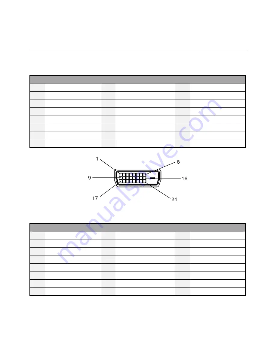
Digital RGB Output (DVI-D): DVI
PIN ASSIGNMENT OF DVI CONNECTOR
01
TX2-
09
TX1-
17
TX0-
02
TX2+
10
TX1+
18
TX0+
03
Shield (TX2 / TX4)
11
Shield (TX1 / TX3)
19
Shield (TX0 / TX5)
04
NC
12
NC
20
NC
05
NC
13
NC
21
NC
06
DDC-Serial Clock
14
+5V power
22
Shield (TXC)
07
DDC-Serial Data
15
Ground
23
TXC+
08
NC
16
Hot plug detect
24
TXC-
Digital RGB Input (DVI-D): DVI
PIN ASSIGNMENT OF DVI CONNECTOR
01
RX2-
09
RX1-
17
RX0-
02
RX2+
10
RX1+
18
RX0+
03
Shield (RX2 / RX4)
11
Shield (RX1 / RX3)
19
Shield (RX0 / RX5)
04
NC
12
NC
20
NC
05
NC
13
NC
21
NC
06
DDC-Serial Clock
14
+5V power
22
Shield (RXC)
07
DDC-Serial Data
15
Ground
23
RXC+
08
NC
16
Hot plug detect
24
RXC-


