


Install Video at
www.DynamicMounting.com/Install
14
Unplug Power Before Adjusting:
The wall mount actuation is very strong, do NOT
run the mount when anyone is near the mount. Do NOT have any part of the body in the mount
or between the TV and Wall. The Mount will keep driving until someone pushes another button
on the remote to stop it. When working on the mount unplug the power.
Figure 16, Tilt Adjust
Set
t
ing the Tilt in the Bottom and Out Positions
In the bottom and out positions the mounts tilt can be set Vertical
+1/-2 degree. To adjust;
1.
Have TV on the mount
2.
Drive mount to Out Position for easiest access
3.
Unplug the power to avoid mount movement
4.
Adjust the bolt shown in Figure 17 with a 1/2" open ended
wrench
Figure 17, Bottom Tilt Adjust
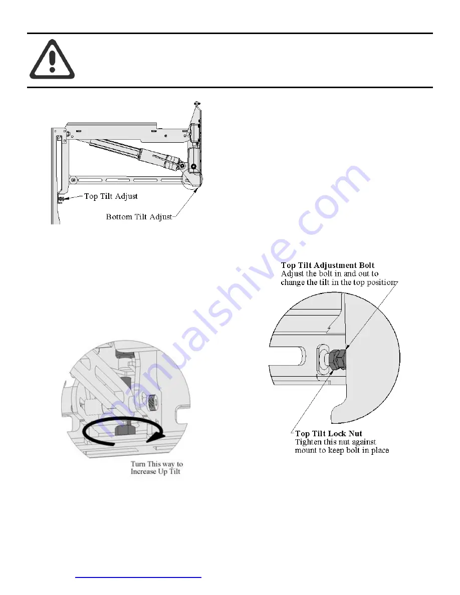
Setting the Tilt in the Top Position
In the top position the tilt will probably have to be adjusted to be
vertical;
1.
Have TV on the mount
2.
Drive mount all of the way to the Top Position (hold
until
mount stops)
3.
Take note of the tilt
4.
Drive mount to Out Position for easiest access
5.
Unplug the power to avoid mount movement
6.
Adjust the screws shown in Figure 18, one on each side
7.
Plug power back in
8.
Drive mount to the Top Position
9.
Repeat As needed
10.
Tighten Lock Nut when Tilt is good
Figure 18, Top Tilt Adjust
Wire Management
Figure 19 shows the suggested wire route to keep the wires hidden with maximum flexibility and free from pinching.


