Embedded Solutions
Page 22 of 37
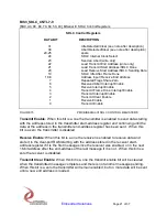
Transmit Interrupt Enable
: When this bit is a one the transmitter interrupt is enabled.
The interrupt will occur at when the transmit state-machine reaches the end address
stored in the transmitter end-address register and there is not another message
pending. When this bit is a zero the interrupt status will still be latched, but will not
cause an interrupt to occur. The transmit interrupt is mapped to the first interrupt line in
its channel block.
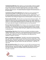
Transmit Frame Done Interrupt Enable
: When this bit is a one the transmit frame
done interrupt is enabled. This interrupt will occur when each message frame
completes regardless of whether another message is pending. When this bit is a zero
the interrupt status will still be latched, but will not cause an interrupt to occur. The
transmit frame done interrupt is mapped to the second interrupt line in its channel block.
Receive Interrupt Enable
: When this bit is a one the receiver interrupt is enabled. The
interrupt will occur at the end of a message transmission, which is determined by the
detection of a SDLC flag character (0x7e) after the message has started. When this bit
is a zero the interrupt status will still be latched, but will not cause an interrupt to occur.
The receive interrupt is mapped to the third interrupt line in its channel block.
Received Abort Interrupt Enable
: When this bit is a one, the received abort interrupt
is enabled. This interrupt will occur when an SDLC abort character (0x7f) is received.
When this bit is a zero the abort interrupt status will still be latched, but will not cause
an interrupt to occur. The received abort interrupt is mapped to the fourth interrupt line
in its channel block.
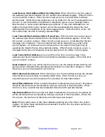
Repeated Flags Share Zero
: When this bit is a one and the transmitter is sending
repeated flag characters, the last zero in each flag will also serve as the first zero in the
next flag. This is only true for two successive flags, the last flag before data is sent will
be sent entirely. When this bit is a zero, all eight bits of each flag will be sent
regardless of adjacent characters.
Address Input/Receive End Address
: This field is used with the three load address
bits to specify address boundaries for the transmitter and receiver data buffers. When
this field is read, it represents the address in which the last received data word from the
last message-frame is stored. Note that this is a 16-bit address, bit 0 indicates which
half of the appropriate long-word the last 16-bit word was stored (0 -> lower half, 1 ->
upper half).
SDLC Idle After Frame Done
: When this bit is a one, the SDLC link will go to the idle
state (minimum of 15 consecutive ones) when message transmission completes. The
link will remain high until a new message is requested. When this bit is zero and the
transmitter remains enabled, the transmitter will send repeated flags until a new
message is requested.


