


14
A setting of 360 degrees on any angle will cause the
control to skip the speed setting that immediately
follows.
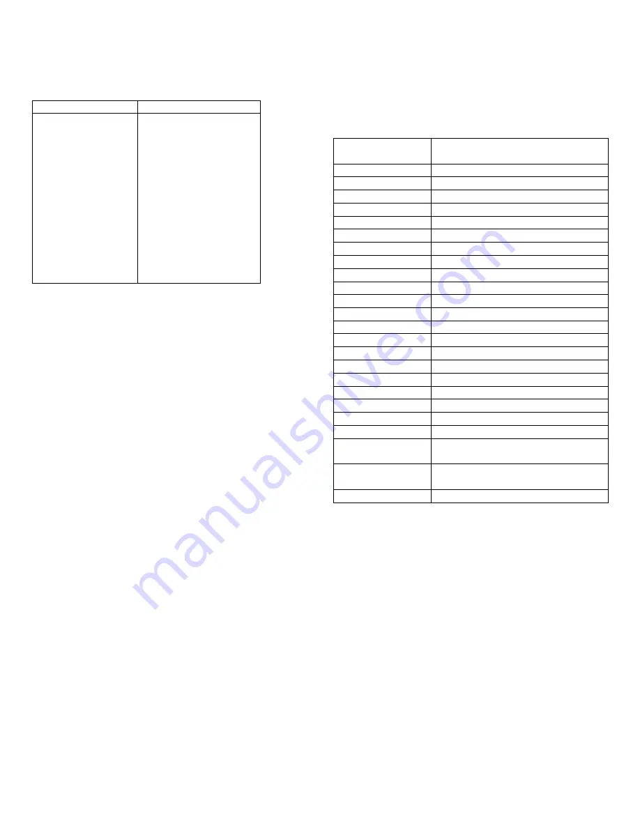
Parameter Locations
Table 2-3
Parameter Number
Data
30
Angle No. 1
31
Speed No. 1 (manual)*
32
Angle No. 2
33
Speed No. 2
34
Angle No. 3
35
Speed No. 3
36
Angle No. 4
37
Speed No. 4
38
Angle No. 5
39
Speed No. 5
40
Angle No. 6
41
Speed No. 6
42
Creep Angle (
α
7)
43
Stop Angle (
α
8)
N0TE: *Parameter No. 31 will be the value of the
Manual Speed pot, if one is used.
While in the run mode, when the press control receives a
stop-on-top command, the CES controller will wait for
the creep angle. Upon reaching the creep angle, the
drive reference will decelerate to the creep speed and
remain at creep speed until the stopping angle is
reached. Upon reaching the stopping angle, the CES
controller will set the reference at 0 and issue a normal
stop signal to the press control. At the same time, the
CES controller will initiate a 450-millisecond timer at the
end, of which the clutch ON signal will be dropped,
dropping out the clutch contactor. Upon receipt of the
normal stop signal, the press control will enable the
friction brake and remove the enable signal. The press
control will remove the enable within 450 milliseconds;
otherwise a stop now fault will be generated.
The 450-millisecond timer is included to ensure that
clutch control excitation is removed regardless of other
sequential operations in the event of some type of fault
or failure.
Certain parameters can only be programmed from the
keypad of the DMR. They are listed on Table 2-4.
The run mode will be indicated by the "Run" LED on the
keypad and display board. Some controls have a full
range manual Run Speed pot, others have a +/-5%
manual Run Speed trim pot, while still others function
without any speed pot. Both pots are effective when the
press starts up and after the press passes Angles No. 1.
II. INCH FORWARD MODE (RUN AT)
The CES controller will be in the inch forward mode if the
following conditions exist:
1. Enable signal is present
2. No fault is present
3. Reverse is not present
4. Inch is present
5. Micro inch is not present
6. Clutch contactor ON signal is present
7. Brake contactor is closed
Keypad Programming
Table 2-4
Parameter
Number
Data
44
Creep Speed
45
Micro Inch Speed
46
Inch Speed
47
Inch Accel Rate
48
Initial Value of Linear Accel Ramp
49
Initial Accel Rate (A1)
50
Operating Accel Rate No. 1
51
Operating Accel Rate No. 2
52
Operating Accel Rate No. 3
53
Accel Rate Delta SPM No. 1
54
Accel Rate Delta SPM No. 2
55
Operating Decel Rate No. 1
56
Operating Decel Rate No. 2
57
Operating Decel Rate No. 3
58
Decel Rate Delta SPM No. 1
59
Decel Rate Delta SPM No. 2
73
Baud Rate
75
Die Contact Angle
78
Gear Ratio
79
Pulses per Revolution
80
Pot Selector
81-Optional
Stop-on-Bottom – Creep Speed
Angle
82-Optional
Stop-on-Bottom – Apply Brake
Angle
83-Optional
Creep Speed Bottom
When in the inch forward mode, the CES controller
functions in the following manner.
The clutch ON command closes the clutch contactor.
The reference ramps from 0 to the inch reference at the
inch acceleration rate. Upon removal of the enable, the
drive reference goes immediately to 0 and the drive
decelerates to zero speed. At the time the enable is
removed, the 450-millisecond clutch safety timer is
initiated. After 450 Milliseconds the clutch contactor is
dropped out by removing clutch ON. The enable signal
should be the last signal received to eliminate faults.
The drive may be jogged in the inch mode by toggling
the enable signal.
The inch forward mode will be indicated by the "Inch"
LED on the keypad and display board.
Summary of Contents for CES
Page 7: ...7 ...
Page 37: ...Page is intentionally blank ...