Leaders in Pipelin
e Survey Systems
C
C
C
-
-
-
S
S
S
C
C
C
A
A
A
N
N
N
2
2
2
0
0
0
1
1
1
0
0
0
SYSTEM MANUAL Version 6.03i
49
As C-SCAN uses an AC detection method, the conductance per square metre is
dependent on an additional factor of coating type. The Detector uses an average value to
give a general indication of conductance and also assumes 1,000
Ω
.cm soil. If a more
definitive value is required, the coating type and soil resistivity can be entered into DCAPP.
If coating resistance is needed then the following values can be used:
Translating into ohms.m
2
Greater than
10,000
Ω
. m
2
Excellent
coating
10,000 to
2,000
Ω
. m
2
Good to fair coating
2,000 to
500
Ω
. m
2
Fair to bad coating
Below
500
Ω
. m
2
Bad to no coating
C-SCAN can display either conductance or resistance.
NOTE:
It is advisable to use conductance rather than resistance when displaying the data
graphically. This is because any section of excellent coating will have a very high
resistance, meaning areas of poor coating will have a low resistance and these
data points will be very close to the horizontal axis, which will be difficult to read.
As conductance is the reciprocal of resistance the opposite becomes true; areas
of good coating will be displayed close to the horizontal axis leaving the poor
coating areas exposed for better identification.
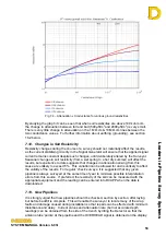
The relationship between attenuation and conductance is complex and the formulae are
derived from extended simulations, manufacturer’s coating data and pipeline steel
characteristics. This relationship is shown in the graph below for soil resistivities of 1,000,
10,000 and 20,000
Ω
.cm
Fig. 7.2 – Attenuation/Conductance for various soil resistivities


