background image

                                                                  2                                                     

 Rev. B

Summary of Contents for 3002 TJ32 Series

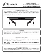
Page 1: ...st paint or any other obstruction which may interfere with the lock and armature making good contact These faces may be cleaned with a non abrasive pad and wiped with an oil dampened cloth The Series 3002xTJ32 is a 1500 pound holding force top jamb mounted electromagnetic lock designed to secure a double inswing door The lock requires both installation procedures as described herein and in the sep...

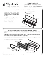
Page 2: ...ng location 1 2 Drill out the six dimpled mounting hole locations inside the back of the lock housing using a 3 16 drill Position the lock assembly on the face of the frame header on the pull side of the door as shown Locate and mark the centers of the mounting holes Drill the marked holes in the face of the frame header Six 6 1 8 dia mounting holes Attach the lock mounting bracket to the frame he...

Page 3: ... may be loosened later for adjustment as necessary Attach the Armature Housing to the top Armature Mounting Bracket using four 4 8 32x3 8 Armature Housing Screws Attach the armature to the armature mounting bracket as shown for LH door Use alternate holes for RH door Firmly tighten the Armature Mounting Screw using a 3 16 hex wrench Failure to properly secure the armature to the bracket could resu...

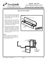
Page 4: ... MOUNTING SCREW LOWER ARMATURE MOUNTING BRACKET 21 32 SEX NUT DOOR SPACER ARMATURE BRACKET MOUNTING SCREW LOWER ARMATURE MOUNTING BRACKET 5 16 18 THREAD Drill an 11 32 diameter hole through door From sex nut side only enlarge the 11 32 hole to 21 32 diameter Drill an 11 32 diameter hole through door From sex nut side only drill 1 2 diameter hole to 1 depth Drill an 11 64 diameter hole and tap for ...

Page 5: ...de the armature in or out to ensure full contact is made with the lock while still allowing the door to properly close and latch When the desired adjustment is achieved slowly open the door taking care to maintain the position of the armature Firmly tighten the armature bracket assembly screws making sure that the locking ribs on the upper and lower bracket halves properly mesh Ref Figure A 1 2 3 ...

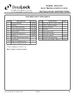
Page 6: ...Upper Armature Bracket 301254 4 Lower Armature Bracket 301260 5 Access Cover 300009 6 8 32x3 8 Machine Screw 300608 7 End Cover 300010 8 1 4 20x1 2 Button Head Screw 9 Lock Washer 10 10x1 Self Tapping Screw 10 10 24x1 2 Machine Screw ITEM DESCRIPTION PART 11 5 16 18x3 4 Arm Screw Turned 12 0 235 L Armature Spacer 14 Flat Steel Washer 15 Sex Nut 16 Door Spacer Tube 17 5 16 18x1 3 4 Bolt 18 Armature...

Page 7: ...INSTALLATION INSTRUCTIONS 02 07 705 Emmett Street Bristol CT 06010 1 877 DynaLock www dynalock com Note Refer to Page 6 for parts legend EXPLODED PARTS VIEW 1 1 2 22 2 3 4 7 3 8 2 3 8 1 2 8 3 4 2 9 16 5 8 1 2 3 4 5 7 6 8 9 10 11 12 14 15 16 17 18 19 ARMATURE ASSEMBLY TYPICAL 20 ...

Page 8: ... FOR PRODUCT SUPPORT AND PARTS ORDERING INFORMATION CONTACT DynaLock Corp 705 Emmett Street Bristol CT 06010 Bus 877 396 2562 Toll Free 860 582 4761 Fax 860 585 0338 DYNALOCK ON THE INTERNET E mail info dynalock com Website www dynalock com UL C R US LISTED GWXT Auxiliary Lock CSFM NYC Mea 23 92 E PLEASE DELIVER THIS MANUAL TO THE END USER UPON COMPLETION OF THE INSTALLATION ...

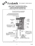
Page 9: ... 3000LC 2000 2050 2280 SERIES CIRCUIT BOARD DESCRIPTION Refer to Page 2 3 for wiring instructions 1 Rev B DynaLock Corp 705 Emmett Street P O Box 2728 Bristol CT 06011 2728 Phone 860 582 4761 Fax 860 585 0338 DynaLock Electromagnetic Locking Systems ...

Page 10: ...2 Rev B ...

Page 11: ...3 Rev B ...

Page 12: ...4 Rev B ...

Reviews: