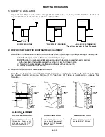
MOUNT THE ARMATURE TO THE DOOR
Failure to properly secure the armature to the door could result in serious injury or possible security breach.
PREPARE THE HEADER FOR LOCK MOUNTING
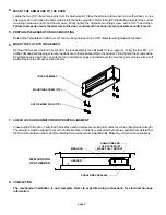
MOUNT THE LOCK TO THE HEADER
CHECK LOCK AND ARMATURE FOR PROPER ALIGNMENT
COMPLETION
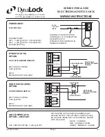
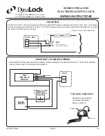
The mechanical installation is now complete. Refer to separate wiring instructions for electrical hook-up
information.
Locate the two 3/16" dia.anti-spin pins from the hardware kit. Place the armature face-down on a soft surface ( i.e. the
shipping carton ) and drive the anti-spin pins into the holes provided. Refer to Note #3 illustrations to select the correct
mounting hardware and mount the armature. Firmly tighten the armature mounting screw with a 3/16" hex wrench.
Refer to the Template and drill four 1./8" dia. mounting holes and one 9/16" diameter wiring hole where shown.
Remove the Access and End Covers from the lock assembly (see Exploded View - page 4). Using the four #10 x 1"
phillips flat head self-tapping screws provided secure the lock assembly to the header. Firmly tighten the screws with a
#2 phillips head screw driver. Locate the four anti-tamper plugs and install over the mounting screw holes with a soft
mallet. Replace the Access and End Covers.
Close and latch the door. Verify that the lock face and armature are making full contact over the entire armature length.
The armature must be aligned to cover the full active face of the lock, represented by the three parallel bars visible from
the front. Should the armature offset holding force will be reduced significantly. Make any corrections as necessary.
be
4.
5.
6.
LOCK ASSEMBLY
MOUNTING SCREW (TYP.)
ANTI-TAMPER PLUG (TYP.)
7.
8.
page 3
ARMATURE AND
LOCK FACE MUST
MAKE FULL CONTACT
MAGLOCK
HEADER
SHOULD BE PARALLEL
VIEW LOOKING
UP AT HEADER


