Dyna-Fog CYCLONE ULTRA 2734, Operation And Maintenance Manual
The Dyna-Fog CYCLONE ULTRA 2734 is a powerful and efficient fogger designed for professional pest control applications. Ensure optimal performance and longevity by following the Operation And Maintenance Manual, available for free download from manualshive.com. Keep your equipment in top condition for reliable results every time.
Share
Download


Reviews:
No comments
Related manuals for CYCLONE ULTRA 2734
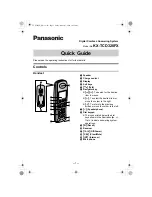
KX-TCD320FX
Brand: Panasonic Pages: 6

ES9455 MFP
Brand: Oki Pages: 50

5274
Brand: National Flooring Equipment Pages: 12

RCM-1201TC-7S
Brand: Ricoma Pages: 49

memory craft 5700
Brand: Janome Pages: 62

Quantum Stylist Touch
Brand: Singer Pages: 4

KX-F2510NZ
Brand: Panasonic Pages: 68

KX-F2581NZ
Brand: Panasonic Pages: 82

KX-F2581AL
Brand: Panasonic Pages: 84

KX-F3000
Brand: Panasonic Pages: 96

KX-F220
Brand: Panasonic Pages: 132

KX-F2681BX
Brand: Panasonic Pages: 146

KX-F230
Brand: Panasonic Pages: 144

KX-F280
Brand: Panasonic Pages: 152

KX-F270
Brand: Panasonic Pages: 152

KX-F2900
Brand: Panasonic Pages: 196

KX-F3100
Brand: Panasonic Pages: 248

kx-ft902
Brand: Panasonic Pages: 20


