22
UVCS LED Light-Curing Conveyor Systems User Guide
Validation
Tests should be conducted prior to production to determine the time and light intensity required to fully
cure your resin. The following approaches may be used to validate the curing process.
Set Exposure Time, Determine Intensity
Users can specify an exposure time and, through empirical testing, determine the intensity required and
duration of exposure to achieve a full cure. Intensity can be adjusted using the front control screen on
each LED Power Supply. Duration of exposure can be adjusted by adjusting the conveyor belt speed. As
with any manufacturing process, it is advisable to incorporate a safety factor.
Control
Process validation confirms a minimum acceptable intensity. Users can then choose to operate at full
intensity (using the excess intensity as an additional safety factor) or adjust the output to a specific
intensity level. To ensure consistent and repeatable process results, intensity levels should be monitored
with a radiometer. This enables users to identify changes in light intensity and take corrective action:
either adjusting the light intensity or performing maintenance.
Cleaning and Maintenance
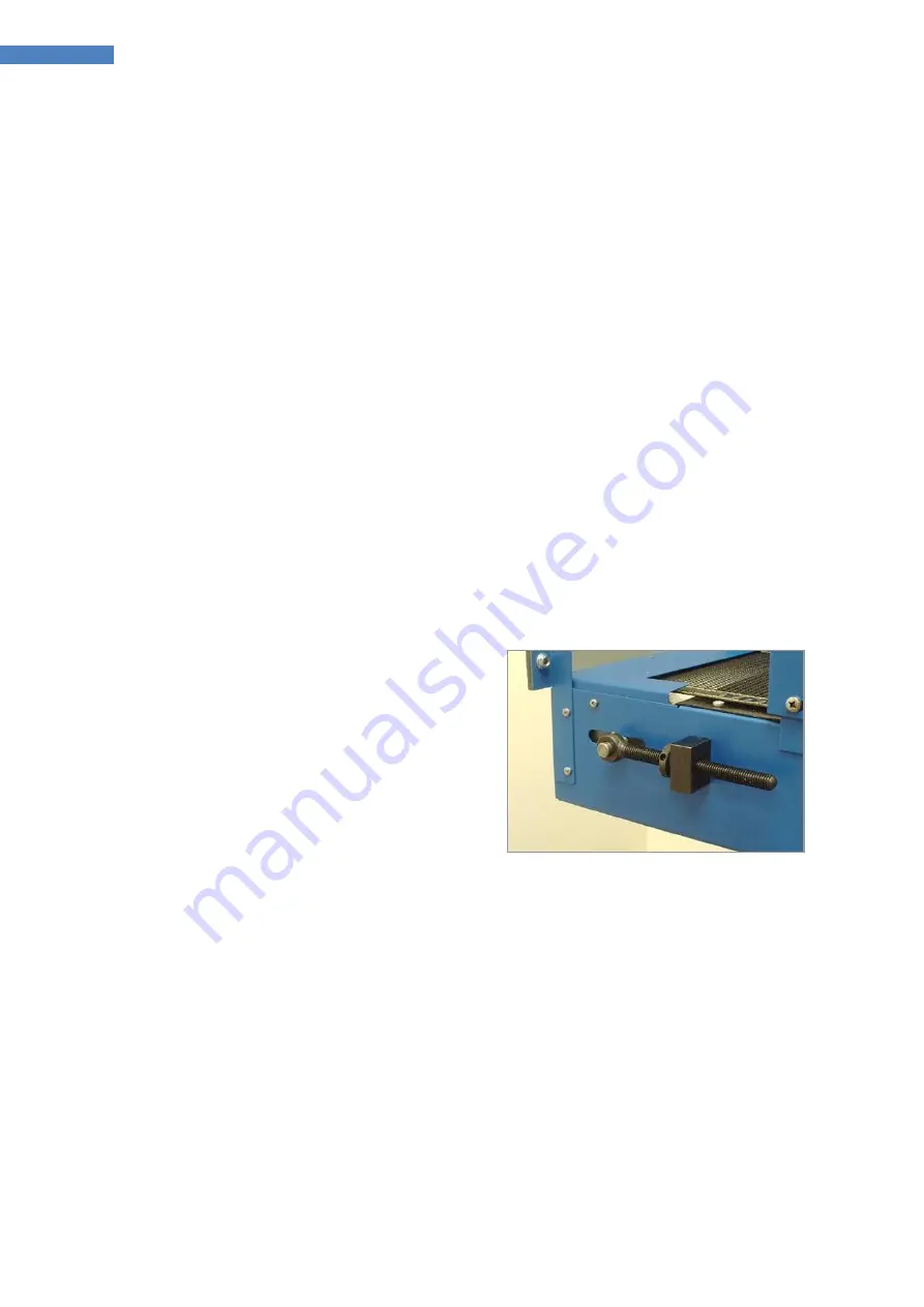
Belt-Tracking Adjustment
All Dymax UVCS conveyors are factory adjusted
to provide proper tracking of the belt. Should
further adjustments become necessary, there
are two knurled adjustment knobs located at
the input end of the conveyor (Figure 31). To
adjust tracking, simply tighten the side to which
the Belt is tracking.
NOTE:
Do not over tighten the belt. This will
lead to accelerated degradation of the belt. The
belt should be stoppable with moderate hand
pressure.
Figure 31. Belt-Tension Adjustment
Knob
Conveyor Belt Replacement
1.
Disconnect the conveyor system from the power source
2.
Remove the pinch guard from the motor side of the conveyor by removing the two M4x8 screws
(Figure 32) on the front side of the conveyor and the M4x25 screw (Figure 33) from the motor-drive
side of the conveyor.
3.
Remove the pinch guard from the input side of the conveyor by removing the three M4x8 screws
(Figure 34) from both sides.


