background image


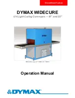
Dymax WIDECURE UV Conveyor 

10 

SYSTEM OPERATION


1.  Turn on the main power to the conveyor (Figure 11).   
  
2. 

Press “START” on the Conveyor Speed Controller (Figure 12). Set the Belt speed by pressing and holding the 
up arrow or down arrow.  Belt speed can be adjusted from 1 to 50 fpm.   

 
3.  Turn Power Supply's main power on. This is done by turning the red knob on the Power Supply Front Panel 

(Figure 13) to the "ON" position. 


Figure 11.

 Main Power Controls 


Figure 12.

 Conveyor Speed 

Controller 


Figure 13.

 Power Supply Front Panel. 


4.   Select “RUN UV” on the Touch Screen Interface (Figure 14). 
 
5.  Turn on the control power to the UV by pushing the green "ON" Button located on the Power Supply Front 

Panel (Figure 13).  


6. 

Select “LAMP ON 400W” on the Touch Screen Interface to start the UV Lamp (Figure 15). "LAMP 
WARMING" will appear at the bottom of the Touch Screen. Once the UV Lamp is ready, 

“LAMP ON 400W” 

will be displayed.  


NOTE:

 The UV Lamp must always be started at 400 W.  After the UV Lamp has warmed up, a lower power 

may be selected if desired.   

 
7.   Adjust the height of the UV Lamp as desired by turning the UV Irradiator

’s Hand Crank (Figure 16).  The 

height of the UV Lamp above the Belt is shown by a Scale mounted on the top of the conveyor so that 
adjustments may be performed without the operator looking into the Curing Chamber.  


Figure 14.

 Select "RUN UV" on 

the Touch Screen Interface.


Figure 15.

 Select "LAMP ON 400W"  

on the Touch Screen Interface. 


Figure 16.

 UV Lamp's Hand Crank & Scale 


8.   After the Power Supply is shut off there is a delay before the UV Blower shuts off.  Do not shut off the power 

to the main machine before the UV Blower shuts off. 


Summary of Contents for 39380

Page 1: ...WIDECURE Conveyor 18 PN39380 25 PN39381 DYMAX WIDECURE UV Light Curing Conveyors 18 and 25 Operation Manual Discontinued System ...

Page 2: ...S Unpacking and Inspection 3 Safety 4 General Description 6 Specifications 7 Installation and System Interconnect 8 Operation 10 System Adjustments 11 Maintenance 12 Troubleshooting 13 Spare Replacement Parts 13 Definition of Terms 14 Warranty 15 ...

Page 3: ...related to conveyor performance replacement parts troubleshooting or repair should be directed to Systematic Automation at 860 677 6400 ext 117 UNPACKING AND INSPECTION Upon receipt of the unit carefully remove the conveyor from the shipping crate and check for damage Dymax is not responsible for damage from shipping all claims for shipping damage should be made with the carrier If you observe or ...

Page 4: ...related to UV light curing systems UV exposure high temperature surfaces ozone and bright visible light UV EXPOSURE Standard Dymax UV light curing systems and bulbs have been designed to primarily emit UVA light as shown in Chart 1 UVA light is generally considered the safest of the three UV ranges UVA UVB and UVC Although OSHA does not currently regulate ultraviolet light exposure in the workplac...

Page 5: ...ed to quickly create workstation shielding This UV blocking flexible urethane film is available from Dymax HIGH TEMPERATURE SURFACES Surfaces exposed to high intensity curing lights will rise in temperature The intensity distance exposure time cooling fans and the type color of the surface can all affect the actual surface temperature In some cases exposed surfaces can reach temperatures capable o...

Page 6: ... System has an External Exhaust Duct that can be attached to standard exhaust ducting External exhaust installation is recommended because the unit produces a small amount of ozone that might be a problem when exhausted to a confined or poorly ventilated space A UV Blower is provided to remove heat and ozone produced by the UV Bulb Ducting for the UV Blower exhaust is provided to the top of the cu...

Page 7: ...26 x 38 x 71 320 cm x 96 5 cm x 180 3 cm 126 x 45 x 71 320 cm x 114 3 cm x 180 3 cm In Feed Length 36 91 4 cm Shroud Length 60 152 4 cm Out Feed Length 36 91 4 cm Clearance and Lamp Height Adjustable from 5 to 24 12 7 cm to 61 0 cm ELECTRICAL INFORMATION UV Lamp Electrical Requirements 220 VAC3 60 Hz 50 Amps 220 VAC3 60 Hz 80 Amps Single phase plus ground Conveyor Electrical Requirements 110 VAC 6...

Page 8: ...l the four threaded Legs into the Conveyor Feet Adjust the threaded Legs as required to level the unit and to set the conveyor Belt working height 2 Provide two sources of AC power to the conveyor See Table 2 for requirements NOTE On the higher voltage models the power sources must be hard wired into the back of the conveyor by a qualified electrician The 115V model has a standard North American w...

Page 9: ...e conveyor Belt Figure 6 Hand Crank System Figure 7 Irradiator Figure 8 Scale 7 The Curing Chamber is surrounded by an enclosure but is open on top There are panels that are screwed onto the Chamber Housing at the entry and at the exit These panels may be removed to allow for taller products to pass thru the Curing Chamber Remove only enough panels to allow your package to enter the Curing Chamber...

Page 10: ...00W on the Touch Screen Interface to start the UV Lamp Figure 15 LAMP WARMING will appear at the bottom of the Touch Screen Once the UV Lamp is ready LAMP ON 400W will be displayed NOTE The UV Lamp must always be started at 400 W After the UV Lamp has warmed up a lower power may be selected if desired 7 Adjust the height of the UV Lamp as desired by turning the UV Irradiator s Hand Crank Figure 16...

Page 11: ... the Belt remains relatively centered between the two Rubber Roller Guides If the Belt requires an adjustment loosen the Jam Nut and Set Screw and turn the Adjustment Screw clockwise to increase Belt tension Make this adjustment equally on both sides of the conveyor to ensure proper Belt tracking Retighten the Jam Nuts and locking Set Screws Do not over tension the Belt Over tensioning can cause t...

Page 12: ... the lamp should now be free on both ends Remove the stainless steel button head screw Figure 3 on one side It does not matter which side you removed Figure 19 UV Lamp Housing Figure 20 Remove Top Nuts on Ceramic Pieces Figure 21 Remove One Stainless Steel Button Head Screw 7 If the irradiator is at an angle be mindful of gravity After the button head screw is removed the lamp can fall depending o...

Page 13: ...wer Switch lights and Motor turns but Belt does not move Verify the operation of the Drive Shaft and Drive Rollers Use the tracking adjustment screws to increase the tension on the Belt Both knobs need to be turned the same amount to maintain alignment Belt Tracks to One Side Belt Adjustment Screws are out of position Visually inspect the Belt The Belt will track to one side Tighten the Belt Adjus...

Page 14: ...are very minute amounts below 220 nm and practically nothing can be sensed below 200 nm This is due to the use of ozone blocking quartz bulb envelope See Ozone 1 Ultraviolet A UV A UV of long wavelength from approximately 400 to 320 nm of the spectral band This is the predominant energy produced by Dymax flood lamps 2 Ultraviolet B UV B UV of medium wavelength from approximately 320 to 280nm Dymax...

Page 15: ...TIVE ACTIONS LISTED BELOW ARE LIMITED TO THIS AUTHORIZATION Dymax offers a one year warranty against defects in material and workmanship on all system components excluding bulbs with proof of purchase date Unauthorized repair modification or improper use of equipment may void warranty The use of aftermarket replacement parts not supplied or approved by Dymax Corporation will void any effective war...

Page 16: ...r performance testing and evaluation by offering equipment trial rental and leasing programs to assist in such testing and evaluations MAN018 01 21 2015 Dymax Corporation 1 860 482 1010 info dymax com www dymax com Dymax Oligomers Coatings 1 860 626 7006 info_oc dymax com www dymax oc com Dymax Asia H K Limited 852 2460 7038 dymaxasia dymax com www dymax com cn Dymax Europe GmbH 49 611 962 7900 in...

Reviews: