DWK Life Sciences | 856.825.1100 |
www.dwk.com
| P/N 50099817 Rev. 11/2021
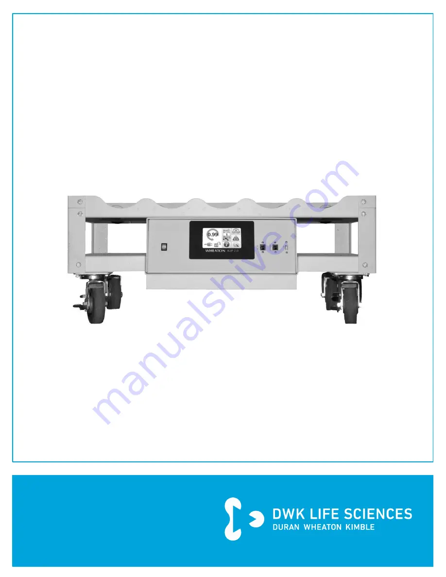
WHEATON® R2P™ 2.0
Bottom Drive Roller Apparatus
INSTRUCTION
MANUAL
Catalog Numbers:
WRBXXXXXX-A
THROUGH
J
Page 1: ...DWK Life Sciences 856 825 1100 www dwk com P N 50099817 Rev 11 2021 WHEATON R2P 2 0 Bottom Drive Roller Apparatus INSTRUCTION MANUAL Catalog Numbers WRBXXXXXX A THROUGH J ...
Page 2: ...17 General Guidelines on Numerical Entry 19 The Home Screen 20 Bottle Speed and Direction Setting 21 Unit Network ID 22 Network Online Offline Icon WSP Protocol Only 22 Alarm Notification Screen 23 Unit Power Icon 24 Unit Screen Lock Icon 24 Information Screen 24 User Setup Screen 25 Speed Ramp Time Screen 26 Temperature Alarm Screen 26 Retrieve Unit Settings Screen 27 Save Unit Settings Icon 28 I...
Page 3: ...hernet TCP IP Network 41 WSP Protocol 43 Modbus Protocol 43 5 ADVANCED OPERATION 45 Enable Disable Internal Event Log Recording 46 Download Event File 46 Sample File 47 File Sorting 47 Delete Event File 48 6 MAINTENANCE FOR QUALIFIED SERVICE PERSONNEL ONLY 49 Instrument Inspection 49 Instrument Maintenance Schedule 49 7 TROUBLESHOOTING 50 Troubleshooting Check List 50 Motor Replacement 52 Fuse Rep...
Page 4: ...C MAIN ASSEMBLY WRBXR5XX0 C J FIGURE D MAIN ASSEMBLY WRBXR5XX1 C J FIGURE E BASE ASSEMBLY WITH UPRIGHTS WL055618 FIGURE F AND G DRIVE UNIT WL058604 WL058639 WL058620 WL058640 FIGURE H FRONT RAIL ASSEMBLY WL055613 FIGURE I REAR RAIL ASSEMBLY WL055612 FIGURE J ROLLER ASSEMBLY WL055614 FIGURE K DRIVE PULLEY SENSORS WL058613 WL058614 FIGURE L MAINS FUSE REPLACEMENT FIGURE M BOTTLE SPEED VALIDATION EMI...
Page 5: ... if desired round out the bottle control A rotation alarm is standard and will warn of a belt or motor failure An optional battery backup allows 18 hours of normal operation if main power is lost Optional resistance temperature detector RTD sensors are available to measure ambient conditions The roller apparatus can be used as a stand alone unit or quickly and inexpensively connected to a TCP IP o...
Page 6: ... weight limit per deck of 30 pounds Use of this equipment for other than its intended purpose shall void this warranty This product is not intended for use in adverse environments outside the environmental conditions listed in this manual It is also not intended for use with corrosive or explosive solutions This warranty is made expressly in lieu of any and all other warranties expressed or implie...
Page 7: ...K Life Sciences takes no responsibility for damage to merchandise in transit All such claims must be submitted to the carrier DWK Life Sciences makes no other express or implied warranty statutory or otherwise concerning materials or goods supplied including without limitation ANY WARRANTY of fitness for a particular purpose or any warranty of merchantability The warranties given are exclusive of ...
Page 8: ... and or serious personal injury An ELECTRICAL DANGER symbol indicates attention to an operation which could cause electrocution or severe injury A Pinch and Crush danger symbol indicates attention to an operation which could cause severe injury due to hands or fingers being caught in rotating parts or machinery This product may use optional rechargeable lead acid batteries Carefully follow the inc...
Page 9: ...p well lighted Be certain the work surface is clean level and sturdy enough to support the weight of the unit particularly if it is to be filled with liquid Wear proper apparel Do not wear loose clothing neckties or jewelry that might get caught in moving parts Non slip footwear is recommended Wear protective hair covering to contain long hair Wear safety goggles Wear safety goggles at all times E...
Page 10: ...URT CIRCUIT ÉLECTRIQUE LA MISE À LA TERRE RÉDUIRA LE RISQUE DE CHOC ÉLECTRIQUE L ÉQUIPEMENT DOIT ÊTRE RELIÉ À LA TERRE This instrument is equipped with a cord having a grounding wire and an appropriate grounding plug The plug must be used with an outlet that has been installed and grounded in accordance with all local codes and ordinances The outlet must have the same configuration as the plug DO ...
Page 11: ...54 RPM using 117 mm diameter bottles Installation Category Class II IP Code Control Head Only 42 Environmental Operating temperature 5 C to 40 C Humidity 80 up to 31 C 50 at 40 C Altitude limit 2000 meters Store and Recall Registers 1 100 Registers Log Event Limit 14 366 events Wrap around will delete 1 024 oldest records Network Communication RS 422 485 Full Duplex Proprietary 9600 8 N 1 9600 bau...
Page 12: ...power switch Signal Alarms Dry contact relay output is energized on normal condition and de energized on alarm condition common to all alarm conditions Audio Alarm Internal audio alarm sounds on alarm condition common to all alarms Can be disabled independent of the signal alarm Dry Contacts Dry contact alarm relay available through the RS 422 485 port See section 4 3 1 for dry contact pin outs Co...
Page 13: ...ION W3488893V2 Battery Backup 18 hour and 2 sensor temperature monitor cable W348887 5 Position Add on Deck Kit Modular Spacing 7 106 in deck to deck W348889 5 Position Add on Deck Kit Production Spacing 6 in deck to deck These are kits designed for customer installation Bottom Drive DECK HEIGHT CHART ABOVE FLOOR Decks Production Spaced Modular Spaced Fixed and Removable Fixed Removable 6 in Betwe...
Page 14: ...r pulleys and that the unit is not dented or scratched Input Power Requirements This equipment is designed to operate from a nominal 100 240V single phase AC power source at 47 to 63 Hz The line voltage fuse label located on the lower rear of the unit shows the input voltage and fuses set for the unit at the factory Power Cord Set This unit has been shipped from the factory with a power line cord ...
Page 15: ...ottle rotation direction and time if in rocker mode bottle speed tolerance profile identification number ramp time bottle diameter motor gear ratio and temperature low and high alarm thresholds Initial Settings Upon first time startup the user should enter the bottle speed settings screen and pause the motor This will make sure the motor does not run at undesirable default values Second the user s...
Page 16: ...The screen saver depicts a moving icon with the current bottle speed direction and rock interval if available as well as the temperature of any connected temperature sensors The screen saver is the only location that displays the calibrated temperature values See section 3 10 for more information on the optional temperature sensors FIGURE 2 SCREEN SAVER Bottle Rotation Direction Temperature sensor...
Page 17: ...ided into three main screens e g the Home screen Setup screen and Factory screen Navigating between the three main screens is done through their respective icons found in the lower corners of each screen From the Home screen press the Setup icon to go to the Setup screen FIGURE 3 HOME SCREEN The Setup screen has icons on both lower corners to navigate back to the Home screen or forward to the Fact...
Page 18: ...paratus 18 DWK Life Sciences 856 825 1100 www dwk com P N 50099817 Rev 11 2021 The Factory screen has icons on both lower corners to navigate back to either the Home screen or to the Setup screen FIGURE 5 FACTORY SCREEN Home Icon Setup Icon ...
Page 19: ... Clear Entry Will clear a numeric entry and restore the previous value Tab Between Number Fields If a parameter requires multiple entries in this case bottle speed and tolerance the Tab button will toggle between fields The active field will normally show GREEN If a value is entered that is outside the range for that specific field the field will turn RED Pause Motor will toggle between running an...
Page 20: ...tle speeds and general network operations if used are performed from the Home Screen FIGURE 7 HOME SCREEN The following is a description of the icons found on the Home Screen Bottle Speed and Direction Unit Network ID Number Set unit on off network Alarm Notification Setup Icon Information Icon Unit Power Status Unit Screen Locked Status Time Left Between Direction Changes HH MM SS ...
Page 21: ...sired values The eraser at the top right of the keypad will clear the value shown in the green background number field The four icons with rounded arrows on the bottom right of the screen are for selecting bottle direction and mode Pressing the top left bottle direction icon with the arrow on the right side will set the bottle rotation direction to clockwise Pressing the top right bottle direction...
Page 22: ...con from the top left shows the Unit Network ID of the unit The Unit Network ID range is 1 2047 Pressing on this icon allows the user to change the unit s network identification number FIGURE 9 UNIT NETWORK ID Numbers can be changed by pressing the desired values on the keypad The eraser icon at the top right of the keypad section will clear the value field If desired the user can pause the motor ...
Page 23: ... icon will appear that represents each active alarm Pressing these individual alarm icons will have no effect as they are only informational Alarm Symbols Belt Alarms 1 and 2 Two magnetic reed switches at the opposite end of the control housing each monitor the pulley rotation of one half of the belt train If either the left or right side of the pulley belt train fails to rotate within two expecte...
Page 24: ...If the machine is running on AC power and not charging batteries either due to no battery option installed or batteries fully charged the icon looks like a standard power cord Unit Screen Lock Icon From the Home Screen the second icon from the bottom left displays whether the screen control is locked or unlocked The screen can only be changed through a network command and is therefore not a toucha...
Page 25: ...where users can access less frequently updated or used settings and functions FIGURE 10 SETUP SCREEN The following is a description of the icons found on the Setup Screen Speed Ramp Time Temperature Alarms Retrieve Unit Settings Store Unit Settings Internal Event Log Recording Download Event Log File Erase Internal Event File Set System Time and Date ...
Page 26: ...bers for the new desired value The erase button on the top right of the keypad section will clear the data field and the pause button will pause the motor s operation In order to exit this screen the user must press either the green check to save all changes or the red X to cancel without saving changes The Speed Ramp Time range is 0 to 20 seconds Temperature Alarm Screen Looking at the Setup Scre...
Page 27: ...e and then press the double arrow tab button to toggle between positive and negative The erase button on the top right of the keypad section will clear the data field and the pause button will pause the motor s operation In order to exit this screen the user must press either the green check to save all changes or the red X to cancel without saving changes Retrieve Unit Settings Screen Looking at ...
Page 28: ...ooking at the Setup Screen this is the fourth icon from the left Pressing this icon brings the user to a screen of numbered icons similar to the retrieve units settings screen Each numbered icon represents a register for saving profile settings Profiles that can be saved in these registers include bottle speed rock times and deviation tolerance bottle diameters ramp rates and temperature profiles ...
Page 29: ...e Pressing on this icon brings up an Are you sure type window in which users must press either the red X to cancel or the green check to confirm the download Further explanation of this icon and its functions are described in the Advanced Operation section of this operator s manual Erase Event Log File Icon From the Setup Screen this is the third icon from the left on the second row This icon is u...
Page 30: ...he data field you wish to change has a green background This green background can be moved between fields by pressing the double arrow tab button on the right side of the keypad section For the Date Field the values should be entered through pressing the keypad numbers in the order of year month and then day For the time field the values are entered through pressing the keypad numbers in the order...
Page 31: ...ry Setting screen Only those who are very familiar with the R2P 2 0 system should enter into the Factory Setting screen and manipulate values Maintenance personnel doing routine maintenance and replacing internal components of the system should familiarize themselves with this section FIGURE 17 FACTORY SCREEN The following is a description of the icons found on the Factory Screen Change Bottle Dia...
Page 32: ...ers produce bottles of different bottle diameters It is not recommended that bottles of different manufacturers be mixed on the same unit if an accurate bottle speed is to be obtained The R2P 2 0 Roller Apparatus relies on the maximum bottle diameter for proper bottle speed indications Traction rings and any outside ridges on the bottle must be considered in calculating the maximum bottle diameter...
Page 33: ...n Sensor Procedure To calibrate each sensor press the icon for the temperature sensor to be calibrated A green dot will appear in the upper left corner of the chosen sensor icon The current uncalibrated temperature will appear in this icon There are two data entry fields above the temperature sensor icons to set the high and low temperature points The field with the blue thermometer sets the low t...
Page 34: ... RATIO Proper motor gear ratio is critical to accurate bottle speed indication Pressing this icon brings the user to a data entry field that displays the current gear ratio The user can only change the number left of the colon Motor Encoder Calibration and Adjustment A routine motor encoder calibration is not required nor recommended Control of the motor is entirely digital and will not drift with...
Page 35: ...rs in the menu selections If the motor is replaced with a motor different than the speed it originally came with it is recommended to consult DWK Life Sciences Technical Service to determine if the Reversed Motor setting is needed Restore Factory Defaults Icon This is the fourth icon from the top left of the display that looks like a green refresh button Pressing on this icon brings up an Are you ...
Page 36: ...d communication protocol Users must press an icon from each column to enable network communication A green dot in the upper left corner of the icons indicates which communication method and protocol are selected Further explanation of this screen and its functions are described in the Network Operation section of this operator s manual Alarm Sound Icon Looking at the Factory Screen this is the sec...
Page 37: ... of the screen By default the brightness is set at maximum as shown Calibrate Screen Pressing the calibrate screen button will reset the X and Y touch coordinates of the screen Major temperature shifts and unit age may affect screen calibration If an attempt to press an icon results especially in an adjacent icon being activated a screen calibrate procedure will correct this issue Follow the instr...
Page 38: ...y into the production area to a minimum All control and monitoring of the unit from the front panel e g bottle speed ramp and reverse rates alarm conditions temperature monitoring optional can be accessed from the unit through a network connection IMPORTANT When connecting the R2P 2 0 Roller Unit to a network a cybersecurity assessment should be conducted to reduce the risk of unauthorized access ...
Page 39: ...dition to shielded cabling to insure FCC and CISPR22 emissions compliance a ferrite should be wrapped around the network cable closest to the unit as possible as shown FIGURE 26 RECOMMENDED NETWORK CABLING A recommended ferrite is Fair Rite 0431164181 Wrap the cable through the ferrite once A ferrite is recommended for all networking to the R2P 2 0 both RS 422 485 and Ethernet Cable Wrapped Ferrit...
Page 40: ...l duplex network Up to 32 units can be connected to a single network line The unit pin out for the RS 422 485 network is shown below FIGURE 27 R2P 2 0 RS 422 485 NETWORK CONNECTIONS In addition to the pins for the RS 422 485 communications two pins 7 and 8 are reserved for a dry contact connection In normal operation the dry contact pins are closed During an alarm condition the dry contacts are op...
Page 41: ...rt or protocol used for MODBUS TCP is port 502 This is not a physical port but a number that is used to route the information to the correct application program The unit is recognized over the network by its Internet Protocol Address or IP address This address is configurable in the protocol settings in the factory setup screen FIGURE 28 TCP IP NETWORK SELECTION The IP address is in Internet Proto...
Page 42: ... and subnet mask These settings will be located in the Internet Protocol properties of your local connection information A suitable IP address has the same first three parts and a different last 4th part Example Settings Computer IP Address Example 192 168 000 001 Subnet Mask Example 255 255 255 000 Default Gateway 000 000 000 000 R2P 2 0 IP Address Example 192 168 000 002 Subnet Mask Example 255 ...
Page 43: ... are read only holding registers can be read and written The registers contain 16 bit binary values The register values are returned in network also known as big endian order depending on the tool used to read the registers byte swapping may be necessary for proper display on standard PC equipment Intel uses little endian ordering Modbus specification advises that register numbering begin with 1 f...
Page 44: ...0010 seconds Calendar Date as seconds from 1 1 2000 4 00011 4 00012 reserved 4 00013 Front Panel Lock Unlock Write the value 5555 decimal to lock the front panel Write the value 0 decimal to unlock the front panel All other values are ignored Reading the register returns the panel s state Modbus over the Ethernet Network The R2P 2 0 comes equipped to interface with Modbus TCP IP also known as Modb...
Page 45: ... ASCII file that records with a date and time stamp any event that changes the operation of the unit User changes such as bottle speed adjustments ramp rates bottle diameter settings and reverse times will be recorded In addition all alarm conditions will be reported at the time of initial fault and initial clear The log file is capable of storing 14 336 events The event log is a circular buffer s...
Page 46: ...lipboard icon with a red X through it indicates the recorder has been turned off FIGURE 31 ENABLE DISABLE EVENT FILE RECORDING Download Event File A USB flash drive must be inserted into the front panel USB port before downloading the event file To initiate the download press the green USB Flash Drive Icon A confirmation message will appear before the download starts The file name downloaded to th...
Page 47: ...ure sensor 2 15 9 C 2012 04 11 09 54 25 Unit 1 ERROR Speed 1 02 RPM 2012 04 11 09 54 26 Unit 1 Bottle speed OK 2012 04 11 09 55 26 Unit 1 Temperature sensor 1 OK 2012 04 11 09 55 26 Unit 1 Temperature sensor 2 OK 2012 04 11 09 55 47 Unit 1 ERROR Speed 1 52 RPM 2012 04 11 09 55 47 Unit 1 Bottle speed OK 2012 04 11 09 57 13 Unit 1 Allowed bottle speed tolerance changed from 0 01 to 0 50 RPM 2012 04 ...
Page 48: ...r a download or erased if power is removed from the unit Event data will continue to append to the file until the file is specifically erased The event file will automatically restart if recording is still on To delete an event file from memory press the Erase Internal Event icon A confirmation message will appear before the erase procedure starts FIGURE 33 ERASE EVENT FILE CONFIRMATION ...
Page 49: ...ON INTERVAL Roller Bearings Roller bearings are greaseless and require no lubrication Inspection is required for physical damage only Once a year Rubber Rollers Check rollers for residue buildup Rollers can be wiped down with Alcohol or a common cleaning agent At each harvest interval Nuts Bolts Hardware Check for general tightness replace missing hardware Once a year Drive Belts black Replace bel...
Page 50: ...REMOVAL OF ANY PROTECTIVE COVERS Troubleshooting Check List Unit will not operate Cause Fuse blown Remedy Replace fuse with proper size and type See section 7 3 on fuse replacement Cause Supply voltage low or at zero Remedy Check house receptacle with a voltmeter Cause On Off power switch in off position Remedy Switch power switch to on position Motor runs but roller s will not turn Cause Drive an...
Page 51: ...eed as required Cause Motor control board defective Remedy Replace defective board Cause Drive motor defective Remedy Replace defective motor Motor fails to maintain constant rotation speed Cause Motor control board defective Remedy Replace defective board Cause Drive motor defective Remedy Replace defective motor Cause Line voltage varying by more than 10 Remedy Have mains checked by a qualified ...
Page 52: ...d remove cover 8 Locate and unplug the motor lead cables and ground wire 9 Using a 3 32 in hex key loosen the set screws securing the drive gears to the motor shaft two per gear and then remove the gears 10 Remove the four screws which were loosened in step 4 11 Carefully remove the motor from the base unit 12 For re assembly reverse the above procedure using new motor Fuse Replacement DANGER BE C...
Page 53: ...s which must be maintained in a fully charged state to insure proper auxiliary operation The charging circuitry charges the batteries whenever the roller apparatus is plugged in and power is applied to it If primary mains power is lost while a roller apparatus is in normal operation the battery back up system will automatically and seamlessly switch the roller apparatus to operate and function nor...
Page 54: ...WHEATON R2P 2 0 Bottom Drive Roller Apparatus 54 DWK Life Sciences 856 825 1100 www dwk com P N 50099817 Rev 11 2021 FIGURE A MAIN ASSEMBLY WRBXR5XX0 A B ...
Page 55: ...2 I051433 SPACER 3 8 IN HEX 6 32 THREAD 0 4 8 12 16 20 24 28 32 11 I052363 1 4 20 X 1 2 IN BOLT HEX HEAD 0 16 32 48 64 80 96 112 128 10 I052273 WASHER STAR 6 INTERNAL TOOTH 0 4 8 12 16 20 24 28 32 9 I052370 WASHER STAR 1 4 IN INTERNAL TOOTH 0 16 32 48 64 80 96 112 128 8 I052861 RAIL SIDE SUPPORT 0 2 4 6 8 10 12 14 16 7B WL055657 RAIL UPRIGHT SINGLE DECK PRODUCTION SPACING 0 0 0 0 0 0 0 0 0 7A WL05...
Page 56: ...N HEX 6 32 THREAD 0 4 8 12 16 20 24 28 32 36 40 11 I052363 1 4 20 X 1 2 IN BOLT HEX HEAD 0 16 32 48 64 80 96 112 128 144 160 10 I052273 WASHER STAR 6 INTERNAL TOOTH 0 4 8 12 16 20 24 28 32 36 40 9 I052370 WASHER STAR 1 4 IN INTERNAL TOOTH 0 16 32 48 64 80 96 112 128 144 160 8 I052861 RAIL SIDE SUPPORT 0 2 4 6 8 10 12 14 16 18 20 7B WL055657 RAIL UPRIGHT SINGLE DECK PRODUCTION SPACING 0 4 8 12 16 2...
Page 57: ...WHEATON R2P 2 0 Bottom Drive Roller Apparatus 57 DWK Life Sciences 856 825 1100 www dwk com P N 50099817 Rev 11 2021 FIGURE B MAIN ASSEMBLY WRBXR5XX0 A B ...
Page 58: ...16 20 24 28 32 13 I052240 SCREW 6 32 X 3 8 IN 0 4 8 12 16 20 24 28 32 12 I052370 WASHER STAR 1 4 IN INTERNAL TOOTH 0 16 32 48 64 80 96 112 128 11 I052363 1 4 20 X 1 2 IN BOLT HEX HEAD 0 16 32 48 64 80 96 112 128 10 I052861 RAIL SIDE SUPPORT 0 2 4 6 8 10 12 14 16 9 WL055614 ASSEMBLY DECK R2P ROLLER 1 2 3 4 5 6 7 8 9 8 WL055613 ASSEMBLY FRONT RAIL 1 2 3 4 5 6 7 8 9 7 WL055612 ASSEMBLY REAR RAIL 1 2 ...
Page 59: ...52240 SCREW 6 32 X 3 8 IN 0 4 8 12 16 20 24 28 32 36 40 12 I052370 WASHER STAR 1 4 IN INTERNAL TOOTH 0 16 32 48 64 80 96 112 128 144 160 11 I052363 1 4 20 X 1 2 IN BOLT HEX HEAD 0 16 32 48 64 80 96 112 128 144 160 10 I052861 RAIL SIDE SUPPORT 0 2 4 6 8 10 12 14 16 18 20 9 WL055614 ASSEMBLY DECK R2P ROLLER 1 2 3 4 5 6 7 8 9 10 11 8 WL055613 ASSEMBLY FRONT RAIL 1 2 3 4 5 6 7 8 9 10 11 7 WL055612 ASS...
Page 60: ...WHEATON R2P 2 0 Bottom Drive Roller Apparatus 60 DWK Life Sciences 856 825 1100 www dwk com P N 50099817 Rev 11 2021 FIGURE C MAIN ASSEMBLY WRBXR5XX0 C J ...
Page 61: ...8 32 12 I051433 SPACER 3 8 IN HEX 6 32 THREADED 0 4 8 12 16 20 24 28 32 11 I052363 1 4 20 X 1 2 IN BOLT HEX HEAD 0 16 32 48 64 80 96 112 128 10 I052273 WASHER STAR 6 INTERNAL TOOTH 0 4 8 12 16 20 24 28 32 9 I052370 WASHER STAR 1 4 IN INTERNAL TOOTH 0 16 32 48 64 80 96 112 128 8 I052861 RAIL SIDE SUPPORT 0 2 4 6 8 10 12 14 16 7B WL055657 RAIL UPRIGHT SINGLE DECK PRODUCTION SPACING 0 0 0 0 0 0 0 0 0...
Page 62: ... 8 IN HEX 6 32 THREADED 0 4 8 12 16 20 24 28 32 36 40 11 I052363 1 4 20 X 1 2 IN BOLT HEX HEAD 0 16 32 48 64 80 96 112 128 144 160 10 I052273 WASHER STAR 6 INTERNAL TOOTH 0 4 8 12 16 20 24 28 32 36 40 9 I052370 WASHER STAR 1 4 IN INTERNAL TOOTH 0 16 32 48 64 80 96 112 128 144 160 8 I052861 RAIL SIDE SUPPORT 0 2 4 6 8 10 12 14 16 18 20 7B WL055657 RAIL UPRIGHT SINGLE DECK PRODUCTION SPACING 0 4 8 1...
Page 63: ...WHEATON R2P 2 0 Bottom Drive Roller Apparatus 63 DWK Life Sciences 856 825 1100 www dwk com P N 50099817 Rev 11 2021 FIGURE D MAIN ASSEMBLY WRBXR5XX1 C J ...
Page 64: ...I052737 BELT ROUND ENDLESS 4 1 2 IN DIA 0 4 8 12 16 20 24 28 32 12 I052714 PULLEY TOOTHED 0 8 16 24 32 40 48 56 64 11 I051433 SPACER 3 8 IN HEX 6 32 THREADED 0 4 8 12 16 20 24 28 32 10 WL058614 ASSEMBLY BASE UNIT MODULAR R2P2 0 230V 1 1 1 1 1 1 1 1 1 9 WL055614 ASSEMBLY DECK R2P ROLLER 1 2 3 4 5 6 7 8 9 8 I052363 1 4 20 X 1 2 IN BOLT HEX HEAD 0 16 32 48 64 80 96 112 128 7 I052370 WASHER STAR 1 4 I...
Page 65: ...IN DIA 0 4 8 12 16 20 24 28 32 36 40 12 I052714 PULLEY TOOTHED 0 8 16 24 32 40 48 56 64 72 80 11 I051433 SPACER 3 8 IN HEX 6 32 THREADED 0 4 8 12 16 20 24 28 32 36 40 10 WL058614 ASSEMBLY BASE UNIT MODULAR R2P2 0 230V 1 1 1 1 1 1 1 1 1 1 1 9 WL055614 ASSEMBLY DECK R2P ROLLER 1 2 3 4 5 6 7 8 9 10 11 8 I052363 1 4 20 X 1 2 IN BOLT HEX HEAD 0 16 32 48 64 80 96 112 128 144 160 7 I052370 WASHER STAR 1 ...
Page 66: ...ER APPARATUS R2P 2 4 WL055623 RAIL UPRIGHT 1 DECK R2P 3 2 I052861 RAIL SIDE SUPPORT 4 2 WI058092 CASTER 3 5 IN NON MARKING WITH BRAKE 5 2 WI058093 CASTER 3 5 IN NON MARKING NO BRAKE 6 16 50027727 1 4 X 5 8 IN WASHER PLAIN STAINLESS STEEL 7 40 I052370 WASHER STAR 1 4 IN INTERNAL TOOTH 8 16 50030016 1 4 20 X 5 8 IN BOLT HEX HEAD 9 24 I052363 1 4 20 X 1 2 IN BOLT HEX HEAD 10 4 WL055622 RAIL UPRIGHT C...
Page 67: ...WHEATON R2P 2 0 Bottom Drive Roller Apparatus 67 DWK Life Sciences 856 825 1100 www dwk com P N 50099817 Rev 11 2021 FIGURE F DRIVE UNIT WL058604 WL058639 WL058620 WL058640 ...
Page 68: ...WHEATON R2P 2 0 Bottom Drive Roller Apparatus 68 DWK Life Sciences 856 825 1100 www dwk com P N 50099817 Rev 11 2021 FIGURE G DRIVE UNIT WL058604 WL058639 WL058620 WL058640 NO NC ...
Page 69: ...OOTH 19 2 50029957 NUT HEX 8 32 20 4 50031560 0 100 CRIMP PIN 21 1 WI056895 ROCKER SWITCH POWER 22 1 WI056892 RJ45 FEMALE PANEL TO RJ45 MALE 1 FT 23 1 WI056891 CABLE USB A TO 1X5 FEMALE 24 1 WI056894 RUBBER PLUG RJ45 25 4 50099832 SUPPORT 26 1 WI056893 CIRCUIT BOARD AND TOUCH SCREEN R2PV2 0 27 1 WI058078 POWER SUPPLY 28 V 2 3 A 80 W 28 1 50099827 CONTROL HOUSING TRAY BOTTOM DRIVE R2P2 0 29 1 WI056...
Page 70: ...L058640 42 1 50099799 LABEL NON RECHARGE BATTERIES WL058639 WL058640 43 8 50030018 NUT HEX 1 4 20 WL058639 WL058640 44 1 50099833 WIRE HARNESS BOTTOM DRIVE R2P2 0 STD WL058639 WL058640 45 1 50099828 WIRE HARNESS DRIVE UNIT BOTTOM DRIVE R2P2 0 46 1 WI056897 RJ45 FEM PANEL TO RJ45 MALE 47 1 I051479 CABLE TIE 48 8 I052370 WASHER STAR 1 4 IN INTERNAL TOOTH WL058639 WL058640 ...
Page 71: ...ve Roller Apparatus 71 DWK Life Sciences 856 825 1100 www dwk com P N 50099817 Rev 11 2021 FIGURE H FRONT RAIL ASSEMBLY WL055613 ITEM QTY DWK NO DESCRIPTION 1 1 WL055617 RAIL FRONT SUPPORT R2P ROLLER 2 6 WL055615 BEARING SLOTTED ...
Page 72: ...ive Roller Apparatus 72 DWK Life Sciences 856 825 1100 www dwk com P N 50099817 Rev 11 2021 FIGURE I REAR RAIL ASSEMBLY WL055612 ITEM QTY DWK NO DESCRIPTION 1 1 WL055616 RAIL REAR SUPPORT R2P ROLLER 2 6 WL055615 BEARING SLOTTED ...
Page 73: ...ww dwk com P N 50099817 Rev 11 2021 FIGURE J ROLLER ASSEMBLY WL055614 ITEM QTY DWK NO DESCRIPTION 1 2 I052885 ROD SUPPORT 2 6 I054128 ASSEMBLY ROLLER SHAFT MODULAR PRODUCTION ROLLER 3 1 50028196 WASHER NYLON 4 2 50029959 WASHER STAR 8 INTERNAL TOOTH 5 2 50029922 SCREW 8 32 X 3 8 IN ...
Page 74: ...WHEATON R2P 2 0 Bottom Drive Roller Apparatus 74 DWK Life Sciences 856 825 1100 www dwk com P N 50099817 Rev 11 2021 FIGURE K DRIVE PULLEY SENSORS WL058613 WL058614 ...
Page 75: ... IN INTERNAL TOOTH 8 2 I052363 1 4 20 X 1 2 IN BOLT HEX HEAD 9 4 I052273 WASHER STAR 6 INTERNAL TOOTH 10 4 I052240 SCREW 6 32 X 3 8 IN 11 4 50029959 WASHER STAR 8 INTERNAL TOOTH 12 4 50029922 SCREW 8 32 X 3 8 IN 13 2 I052719 BELT DRIVE 225L025 14 1 50028829 LABEL PINCH AND CRUSH 15 2 I050990 ASSEMBLY TRIP PULLEY MAGNETIC 16 4 50029863 WASHER STAR 4 INTERNAL TOOTH 17 4 50029858 SCREW 4 40 X 3 8 IN ...
Page 76: ...PLACEMENT 1 Remove line cord from unit 2 Use a small flat tipped screwdriver to remove fuse drawer from unit 3 Remove fuse from drawer Replace with fuse type 110 120VAC 1 1 0AT 250V 5x20mm 220 240VAC 2 0 63AT 250V 5x20mm 4 Reinsert fuse drawer and line cord into unit 110 120 VAC 1 1 0 A 250 VAC 5X20 MM 220 240 VAC 2 0 63 A 250 VAC 5X20 MM ...
Page 77: ...WHEATON R2P 2 0 Bottom Drive Roller Apparatus 77 DWK Life Sciences 856 825 1100 www dwk com P N 50099817 Rev 11 2021 FIGURE M BOTTLE SPEED VALIDATION ...
Page 78: ...ate EU Directive with respect to the design and construction of the commercialized version This declaration is invalid if modifications are performed on the device which has not been certified by DWK Life Sciences LLC Designation of the device R2P 2 0 Roller Directives EN61326 1 2006 Standards UL61010 1 CSA C22 2 No 61010 1 Title 47 of the Code of Federal Regulation CFR Part 15 Subpart B for a Cla...
Page 79: ... discarded in typical trash outlets This unit is to be discarded according to WEEE guidelines established in your area There are no reusable parts Contact the original distributor from which this product was purchased for proper disposal instructions R2P is a trademark of DWK Life Sciences LLC Specifications subject to change without prior notice ã2021 DWK Life Sciences LLC ...
Page 80: ...s 80 DWK Life Sciences 856 825 1100 www dwk com P N 50099817 Rev 11 2021 Contact us at DWK com 2021 DWK Life Sciences The trademarks used are owned by DWK Life Sciences GmbH DWK Life Sciences LLC or DWK Life Sciences Ltd 001 EN WMAN_014 50099817 ...