5
Installation and Set-Up
(continued)
T
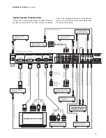
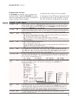
ypical System Configuration
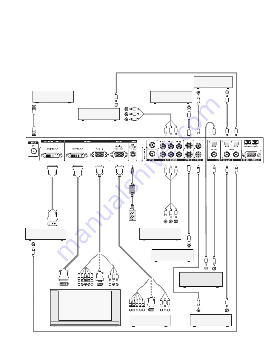
Th
e iScan HD
+
is usu
ally placed between the display device and
any video sources and acts as the source switch for the display.
Shown in this connection diagram are nine audio/video
sources, four of which have digital audio outputs along
with analog video outputs.
DVI-D
DVI-D
DVI-D
Progressively Scanned TV or Projector
Universal
Power Adaptor
AC Mains
(100-240 VAC
50/60 Hz)
Co
m
pon
en
t
V
ide
o
C
ab
le
S-V
ide
o
C
ab
le
Co
m
posite
V
ide
o
C
ab
le
S-V
ide
o
C
ab
le
Co
m
posite
V
ide
o
C
ab
le
D
ig
ital A
u
di
o
Ca
b
le
(O
pti
cal
)
D
ig
ital A
u
di
o
Ca
b
le
(C
oa
xia
l)
D
ig
ital A
u
di
o
Ca
b
le
(C
oa
xia
l)
D
ig
ital A
u
di
o
Ca
b
le
(C
oa
xia
l)
Component Video Source
(480i, 480p, 720p, or 1080i)
YPbPr
VCR or Other
S-Video Source
Component Video Source
(480i, 480p, 720p, or 1080i)
Set-Top Box or Other
DVI source
HD Satellite TV Tuner, PC, or
Progressive-Scan DVD Player
5x
B
NC
3x
R
CA
or
or
Video Game or Other
Composite Video Source
Set-Top Box or Other
S-Video Source
Video Game or Other
Composite Video Source
DVI-D
Audio/Video Preamplifier/
Processor or AV Receiver
Component
Video Cable
D
ig
ital A
u
di
o
Ca
b
le
(O
pti
cal
)
D
ig
ital A
u
di
o
Ca
b
le
(O
pti
cal
)
Y
P
b
Pr
Digital Audio Cable (Optical)
H
D
V
ide
o
DVI-D
or
DVI-I
I
nt
er
fa
ce
Ca
b
le
DVI-D
or
DVI-I
Int
er
fa
ce
Ca
b
le
H
D
V
ide
o
5x
B
NC
3x
R
CA
or
or
HD15
HD15
HD15
HD15
Rear View of
iScan HD+
*
B
N
C
Ca
b
le
DVD Player or Other
SDI* source
*
SDI Video Input Module required
D
ig
ital A
u
di
o
Ca
b
le
(C
oa
xia
l)


