background image

8.2 

Troubleshooting

8.2.1  Replace needle and nozzle.

 NOTICE!

Property damage due to improper
replacement of needle and nozzle

Replacing only the needle or only the

nozzle could damage spray gun compo-

nents. This can compromise the tightness

of the spray gun. The spray pattern deteri-

orates.
– Observe order of replacement steps

(needle  – nozzle).

– Observe order of assembly steps

(nozzle  – needle).

– Always replace nozzle and needle at

the same time.

The integrated Quick Clip technology allows

for removal and installation of the needle

without changing the preset needle stop.
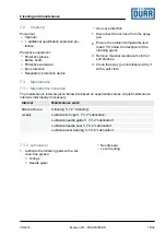
Personnel:

Operator
 + additional qualification explosion pro-
tection

Protective equipment:

Protective gloves
Safety boots
Protective workwear
Eye protection
Respiratory protection device
Use ear protection

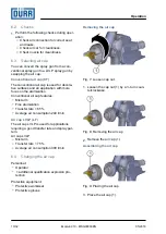
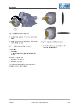
Removing the needle

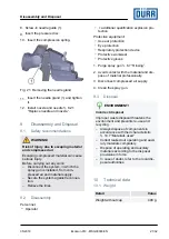
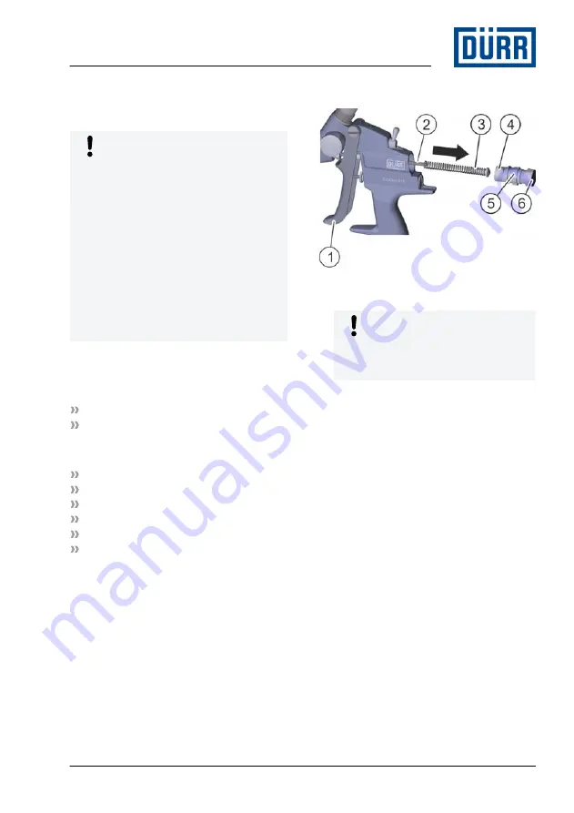
Fig. 13: Replacing the needle

1.

 NOTICE!

The stop screw is spring pretensioned.

When you loosen the stop screw it

might fall off.

Hold onto stop screw (6) while removing

it.

2. Counter the locknut (5) on the clip (4).

3. Press the stop screw (6) on the face by

about 1 mm into the spray gun.

4. Turn stop screw (6) ¼ turn counter clock-

wise.

ð

The spring on the needle (2) pushes
the stop screw (6) out.

5. Pull out the stop screw (6).

6. Remove the compression spring (3).

7. Pull back the trigger (1).

Faults

05/2018

EcoGun 910 - MSG00003EN

17/32

Summary of Contents for EcoGun 910

Page 1: ...EcoGun 910 Manual Air Spray Gun Gravity Feed MSG00003EN V06 N36200003V www durr com Operation manual ...

Page 2: ...plete documentation Always follow safety instructions han dling instructions and specifications of every kind Illustrations can deviate from the tech nical construction Validity range of the document This document describes the following product N36200003V EcoGun 910 Hotline and Contact If you have queries or would like technical information please contact your dealer or sales partner 05 2018 EcoG...

Page 3: ...dations 12 6 7 2 General notes 12 6 7 3 Rinsing spray gun 12 7 Cleaning and maintenance 13 7 1 Safety recommendations 13 7 2 Cleaning 15 7 3 Maintenance 15 7 3 1 Maintenance schedule 15 7 3 2 Lubrication 15 8 Faults 16 8 1 Defects table 16 8 2 Troubleshooting 17 8 2 1 Replace needle and nozzle 17 8 2 2 Replacing valve seal 19 8 2 3 Replace needle gland 20 9 Disassembly and Disposal 21 9 1 Safety r...

Page 4: ... 5 Commissioning Spray width Ä 5 Commissioning The spray gun uses a self adjusting needle package This self adjusts for the material related wear of the sealing package 2 Safety 2 1 Presentation of Notes The following notes can appear in this instructions manual DANGER High risk situation that can lead to serious injuries or death WARNING Medium risk situation that can lead to serious injuries or ...

Page 5: ...at static electricity can be dis charged Use exclusively compressed air quick couplings for water based materials where it is not necessary to keep dis charging static electrical charges 2 3 Residual risks Explosion Sparks open flames and hot surfaces can cause explosions in explosive atmospheres Serious injuries and death can be the conse quence Before carrying out any work ensure a non explosive...

Page 6: ...e the operator possesses the fol lowing knowledge Technical Measures for occupational safety and health The operator is responsible for the following work Operate and monitor the system product Introduce measures in the event of faults Clean system product additional qualification explosion pro tection In addition to the knowledge of the various specialist fields the mechanic has knowl edge of reg...

Page 7: ... to the spray gun and secure it against reconnection The compressed air supply must be adjustable Lines seals and screw connections must be designed to conform to the spray gun requirements Ä 10 Technical data The workplace must have technical venti lation Working environment and grounding Flooring of the working areas must be anti static according to DIN EN 50050 1 2014 03 measurement according t...

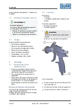
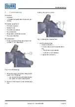
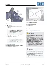
Page 8: ... 4 2 Assembly Fig 3 Commissioning 1 Rinse the spray gun before filling it with paint Ä 6 7 Rinsing use solvent for solvent based paints use water for water based paints 2 Set air control lever 1 into vertical posi tion Setting the spray pattern Fig 4 Setting the material flow 1 Set the material flow Loosen locknut 1 Turn set screw 2 in required direc tion Right turn less material Left turn more ma...

Page 9: ...eristic curve CF Conventional air cap LF Air cap LVLP 6 Operation 6 1 Safety recommendations WARNING Danger of explosion due to chemical reactions Material halogenated hydrocarbon based rinsing agent or cleaning agent can chemi cally react with aluminum components of the product Chemical reactions can cause explosions Serious injuries and death can be the consequence Only use rinsing agents and cl...

Page 10: ...t arm Fine atomization Transfer rate 65 Average air consumption 240 l min Air cap LVLP LF The air cap LVLP is used for applications requiring a good transfer rate and spray pat tern Air cap LVLP Mist arm Transfer rate 75 Average air consumption 300 l min 6 4 Changing the air cap Personnel Operator additional qualification explosion pro tection Protective equipment Protective workwear Protective gl...

Page 11: ...of the air cap Personnel Operator additional qualification explosion pro tection Protective equipment Protective workwear Protective gloves The position of the air cap determines the direction of the spray pattern Fig 11 Alignment of the air valve 1 Turn the air cap as required for the desired spray pattern Operation 05 2018 EcoGun 910 MSG00003EN 11 32 ...

Page 12: ... damage due to unsuitable rinsing agent If the rinsing agent reacts chemically with the components or the material compo nents get damaged Use only the rinsing agents that are compatible with the components and the material Refer to safety data sheet of material manufacturer 6 7 2 General notes When rinsing use fluid to remove inner soiling from components 6 7 3 Rinsing spray gun NOTICE Material d...

Page 13: ... channels are blown free 7 Cleaning and maintenance 7 1 Safety recommendations WARNING Danger of fire and explosion Flammable coating materials and their detergents and cleaning agents can cause a fire or an explosion Ensure that the flashpoint of the fluid is at least 15 K above the ambient tem perature Note explosion group of the fluid Follow safety data sheets Ensure that forced ventilation and...

Page 14: ...by the material manufacturer Follow safety data sheets Place heavily soiled components in a cleaning bath Only place those parts in the cleaning bath which are suitable for the cleaning bath Use only electrically conductive containers Ground the container Do not use ultrasound baths Use alcohols isopropanol butanol for non flammable coating materials Remove dried non flammable coating materials us...

Page 15: ...refully and dry it with a soft cloth 7 3 Maintenance 7 3 1 Maintenance schedule The maintenance intervals given below are based on experiential values Adjust maintenance intervals individually if necessary Interval Maintenance work after each use Cleaning Ä 7 2 Cleaning weekly Lubricate O rings Ä 7 3 2 Lubrication Lubricate needle guide Ä 7 3 2 Lubrication Lubricate needle seal Ä 7 3 2 Lubrication...

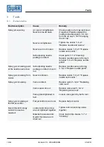
Page 16: ...ew Self adjusting needle package is defect or worn out Replace needle seal and O ring Ä 8 2 3 Replace needle gland Spray gun is leaking from nozzle Nozzle is broken Replace nozzle Ä 8 2 1 Replace needle and nozzle Spray gun is leaking Valve is defect Replace valve Ä 8 2 2 Replacing valve seal Valve seal worn out Replace valve seal Ä 8 2 2 Replacing valve seal Valve gland tightened to fast Loosen v...

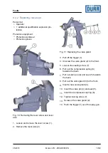
Page 17: ...eset needle stop Personnel Operator additional qualification explosion pro tection Protective equipment Protective gloves Safety boots Protective workwear Eye protection Respiratory protection device Use ear protection Removing the needle Fig 13 Replacing the needle 1 NOTICE The stop screw is spring pretensioned When you loosen the stop screw it might fall off Hold onto stop screw 6 while removing...

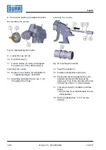
Page 18: ...semble and align the air cap Ä 6 4 Changing the air cap Inserting the needle Fig 15 Inserting the needle 14 Insert the needle 1 15 Position compression spring 2 16 Press stop screw 5 against the com pression spring into the body of the spray gun One of the nibs 6 of the clip 3 must be in the 11 o clock position 17 Turn stop screw 5 clockwise until fas tened ð Stop screw 5 is pushed back into its i...

Page 19: ...e gland 3 Pull off the trigger 1 4 Unscrew the valve gland 2 to the front 5 Loosen the sealing screw 7 6 Pull out the compression spring 6 towards the back 7 Pull out valve pin 4 and seal 5 towards the back 8 Pull out the valve gland 3 to the front 9 Insert a new valve gland 3 10 Insert the valve pin 4 and seal 5 11 Insert the Compression spring 6 12 Tighten locking screw 7 13 Screw in the valve g...

Page 20: ...le and nozzle Ä 8 2 1 Replace needle and nozzle Fig 19 Removing the needle gland 2 CAUTION The compression spring is pre ten sioned Risk of injury Remove the needle gland 1 carefully and relieve the compression spring slowly 3 Remove the compression spring 4 Remove the pressure disc Fig 20 Removing the needle guide 5 Unscrew the needle guide 1 to the front 6 Remove the O rings 2 and seals 3 7 Inst...

Page 21: ...pro tection Protective equipment Use ear protection Eye protection Respiratory protection device Protective workwear Protective gloves 1 Purge spray gun Ä 6 7 Rinsing 2 Avoid contact with the material and dis pose of material professionally 3 Disconnect compressed air supply 4 Clean the spray gun 9 3 Disposal ENVIRONMENT Incorrect disposal Improper waste disposal threatens the environment and prev...

Page 22: ...LpA 77 dB A Uncertainty KpA 5 dB 10 5 Operating values Detail Value Max air pressure 8 bar Detail Value Recommended air pres sure 2 0 3 0 bar Air consumption Example Nozzle bore 1 4 mm Air control maximum Circular jet Detail Value Conventional air cap CF 2 5 bar 10 3 m h 171 0 Nl min Air cap LVLP LF 2 5 bar 10 7 m h 178 0 Nl min Flat jet Detail Value Conventional air cap CF 2 5 bar 16 7 m h 278 0 ...

Page 23: ...al FEPM PTFE Seals without mate rial contact FEPM PE POM 10 8 Operating and auxiliary materials Material Material no Grease Tube Syn theso Glep1 100 g for seals and threads W32020010 10 9 Material specification Suitable material Water based or solvent based paints No materials containing organo chlorine compounds e g trichloro ethane chloromethane Technical data 05 2018 EcoGun 910 MSG00003EN 23 32...

Page 24: ...11 Replacement parts and accessories 11 1 Spare part Fig 22 Exploded view Replacement parts and accessories 05 2018 EcoGun 910 MSG00003EN 24 32 ...

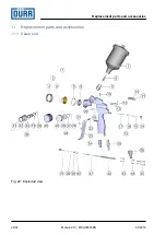
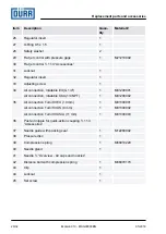
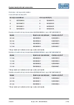
Page 25: ... 3 8 with filter 125 ml 1 N08010032 08 Filter 1 M13010029 09 Cup connection G 3 8 1 10 Locking screw 1 M41090173 11 Blind plug Ä 11 3 Accessories 12 Air control 1 M21200001 13 O Ring 7 0 x 1 5 3 M08030771 14 Locking screw 1 15 Compression spring 1 16 Seals on valve 1 M08280031 17 Valve pin 1 M49150001 18 Valve EcoGun AS MAN 1 19 Seal 1 M08280028 20 Valve gland 1 21 Lever screw 1 22 Lever axle 1 23...

Page 26: ...M01200002 35 Air connection Turn Tilt EU 10 mm 1 M01300001 Air connection Turn Tilt US 8 mm 1 M01300002 Air connection Turn Tilt ASIA 11 mm 1 M01300003 36 Push on nipple for quick action coupling Ä 11 3 Accessories 37 Needle guide with packing seal 1 M12280002 38 Pressure disc 1 39 Compression spring 1 M68010220 40 Needle gland 1 41 Needle Ä Overview Air caps and nozzles 42 Distance bolt with comp...

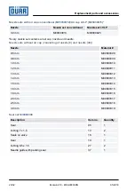
Page 27: ...ins an air cap nozzle and needle Nozzle sets with air cap conventional M35030070 Air cap LVLP M35030074 Nozzle Nozzle set conventional Nozzle set LVLP 1 3 mm M09800006 M09800018 1 4 mm M09800007 M09800019 1 5 mm M09800008 M09800020 1 6 mm M09800009 M09800021 Every nozzle set contains an air cap nozzle and needle Nozzle sets with air cap conventional M35030071 Air cap LVLP M35030075 Nozzle Nozzle s...

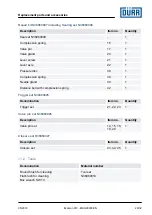
Page 28: ...le 40 Nozzle Material 0 5 mm M09800308 0 8 mm M09800309 1 0 mm M09800310 1 2 mm M09800311 1 3 mm M09800312 1 4 mm M09800313 1 5 mm M09800314 1 6 mm M09800315 1 8 mm M09800316 2 0 mm M09800317 2 5 mm M09800318 3 0 mm M09800319 Seal set N36960008 Description Item no Quantity Seal 05 1 O Ring 7 x 1 5 13 2 Seals on valve 16 1 Seal 19 1 O Ring 9 5 x 1 5 27 2 Needle guide with packing seal 37 1 Replacem...

Page 29: ... bolt with compression spring 42 1 Trigger set N36960025 Denomination Item no Quantity Trigger set 21 22 23 1 Valve pin set N36960026 Description Item no Quantity Valve pin set 14 15 18 19 20 1 Closure set N36960027 Description Item no Quantity Closure set 43 44 45 1 11 2 Tools Denomination Material number Round brush for cleaning Flat brush for cleaning Box wrench SW 13 Tool set N36960014 Replace...

Page 30: ...on Item no Quan tity Material no O Ring 7 0 x 1 5 13 1 M08030771 Safety washer 28 1 Locknut 31 1 Regulator insert 32 1 Adjusting screw 33 1 Push on nipple for quick action coupling Denomination Item no Quan tity Material no Push on nipple for quick action coupling fixed D7 2 d10 12 EU 36 1 M01010185 Push on nipple for quick action fixed D5 d8 11 US 36 1 M01010186 Push on nipple for quick action co...

Page 31: ...elines can cause explosions in an explosive atmos phere Serious injuries and death can be the consequence Use exclusively original replacement parts Ordering replacement parts tools and accessories as well as information on prod ucts that are listed without order number Ä Hotline and Contact Replacement parts and accessories 05 2018 EcoGun 910 MSG00003EN 31 32 ...

Page 32: ... www durr com Phone 49 7142 78 0 Transmission and duplication of this document as well as use and sharing of its contents are not permitted without express written approval Violations will be liable for compensation for damages All rights in the event of a patent grant or design registration are reserved Dürr Systems AG 2015 www durr com ...

Reviews: