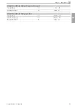


1036100102L02 1904V002
27
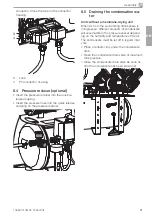
Assembly
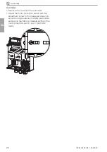
10 Circuit diagrams
10.1 Unit 1036100100
Q1
Q2
X2
M1
X5
M2
M3
M4
5 3 1
6 4 2
P>
L1/L2/L3/N/PE
2 4 6
1 3 5
2 4 6
1 3 5
3 2 1 PE 6 4
13 21
14 22
Q3
X3
2 4 6
1 3 5
3 2 1 PE 6 4
13 21
14 22
3~
3~
1~
1~
A1
X1
X4
4 4 4 5 5 5
PE
PE
2 2 1 1
A1
A2
K1
I> I> I>
I> I> I>
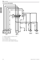
X5 Mains connection 3/N/PE AC 230 V
Q1 Pressure switch
A1 Control box
X1 Distributor rail
X2 Compressor plug connection
X3 Compressor plug connection
X4 Distributor rail
Q2 Motor protection switch
Q3 Motor protection switch
K1 Time-lag relay
M1 Compressor unit
M2 Compressor unit
M3 Fan motor, membrane drying unit (optional)
M4 Fan motor, membrane drying unit (optional)
EN
Summary of Contents for H2A-160M
Page 2: ......


