14
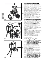
This may otherwise impair proper
functioning of the safety valve.
9. CIRCUIT DIAGRAMS
9.1 Version 1/N/PE AC230 V
List of Equipment
Q1
Pressure switch/motor
protection switch
X1
Mains connection 1/N/PE AC 230 V
M1
Compressor motor
M2
Proposed fan connection
(can be allocated if required)
9.2 Version 3/N/PE AC 400 V
List of Equipment
Q1
Pressure switch/motor
protection switch
X1
Mains connection 3/N/PE AC 400 V
10
11


